background image

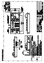
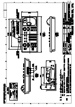
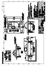
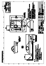
Apr.23'07 R.Esumi

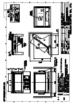
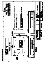
D-13

Summary of Contents for 2137S

Page 1: ...Unit 2 7 2 4 Processor Unit 2 8 2 5 Power Supply Unit 2 12 2 6 Changing AC Power Specification of Processor Unit 2 12 3 SETTING AND ADJUSTMENT 3 1 3 1 DIP Switch Setting 3 1 3 2 Initializing Tuning 3...

Page 2: ...butor Dealer 9 52 Ashihara cho Nishinomiya 662 8580 JAPAN Telephone 81 0 798 65 2111 Fax 81 0 798 65 4200 A APR 2004 Printed in Japan All rights reserved L APR 12 2011 Pub No IME 35210 L 00014868819 0...

Page 3: ...lf to the transmitting antenna at a close distance Distances at which RF radiation level of 100 50 and 10 W m are given in the table below Note If the antenna unit is installed at a close distance in...

Page 4: ...a different cable is used Connection of an incorrect power supply can cause fire or damage the equipment Use only the specified power cable Water in the units can result in fire electrical shock or da...

Page 5: ...gnal cable RW 9600 CP03 25720 000 080 437 50 m signal cable RW 9600 CP03 25730 000 082 191 1 40m signal cable RW 9600 CP03 25800 000 080 434 1 Cable assy for monitor unit CP03 25602 008 535 940 1 For...

Page 6: ...al radar 5 m 8 8P S03 9 10 008 206 650 For external radar 10 m 8 8P Cable Assy S03 9 15 008 209 160 For external radar 15 m 8 8P CP03 28900 000 082 658 FR FTPC CY 10 m CP03 28910 000 082 659 FR FTPC C...

Page 7: ...more than 100 m Not available for HSC spec Switching HUB HUB 100 1 SDME Speed Log 2 3 Contact output for Alarm Load current 120mA Polarity No 1 2 Normally Close No 3 4 Normally Open Serial I O for ala...

Page 8: ...the sticker which is pre attached on the processor unit according to your radar s specification Refer to the table shown below to confirm your category Category Radar Type Antenna rotation speed CAT...

Page 9: ...uld hit the surface of the sea in not more than 500 m or twice the ship s length depending which value is smaller for all load and trim conditions less than 500 m or twice the ship s length Mount the...

Page 10: ...der antenna clear of the antenna unit to prevent interference to the direction finder A separation of more than two meters is recommended A magnetic compass will be affected if the antenna unit is pla...

Page 11: ...s vibration and rolling This exerts excessive levels of stress at the base of the radiator which can damage the radiator To prevent this relocate the antenna unit or if relocation is not possible rein...

Page 12: ...3 Grease O ring and set it to the groove of the choke guide 4 Place the radiator on the radiator bracket Radiator direction is shown by the logo on the bracket If reversely oriented the radiator cann...

Page 13: ...the ropes A and B Lifting fixture Collar for fixing Supplied as accessories Remove after installation Hex bolt M12x20 Torque 63 5Nm Remove lifting fixture coat threads of hex bolts with silicone grea...

Page 14: ...reinforcement ribs 2 Place the corrosion proof rubber mat supplied on the mounting platform 3 Hoist the antenna unit as shown on page 1 5 and place it on the rubber mat Orient the cable gland toward t...

Page 15: ...silicone sealant Ground wire Welding Hex nut Ground terminal provided on antenna base Set corrosion proof rubber mat bolt antenna unit to mounting location and coat exposed hardware with silicone sea...

Page 16: ...heat sources because of heat that can build up inside the cabinet Locate the equipment away from places subject to water splash and rain Leave sufficient space on the sides and rear of the unit to fa...

Page 17: ...ting of monitor unit Panel hook Panel cover Fixing screw Attaching panel hook and panel cover Note If you need to remove the monitor unit from the mounting panel remove the four panel covers with your...

Page 18: ...nger stay with two hex bolts M10x30 flat washers and spring washers and cover each hex bolt with hole plug 2 Fix the above assembly to the mounting location with four hex bolts M12 dockyard supply 3 F...

Page 19: ...21 FP03 11501 001 020 120 1 For FAR 2137S Hood 23 FP03 11001 008 571 700 1 For FAR 2837S Fixing plate 03 163 2202 0 100 335 560 10 4 Screw M4x10 D 13 US304 000 862 543 4 1 Desktop mounting Fasten the...

Page 20: ...e mount display unit the PSU 007 can be installed inside the console However select a dry and well ventilated location and observe the compass safe distance to prevent deviation of a magnetic compass...

Page 21: ...h and rain Determine the mounting location considering the length of the signal cable between the control unit and the processor unit The signal cable comes in lengths of 10 m A magnetic compass will...

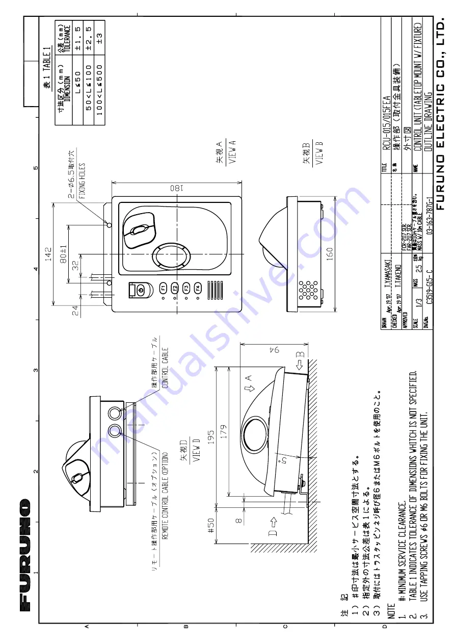
Page 22: ...ided locally 70 308 1 398 136 1 180 4 M4 Fixing holes bottom Control Unit RCU 014 F4 F3 F2 F1 180 24 32 110 1 160 136 1 4 M4 Fixing holes REAR RCU 015 016 Flush mounting Use the optional flush mount k...

Page 23: ...et the control unit to the cutout 3 Attach the mounting plate to the control unit with four screws from the rear side 4 Screw the wing screw to each mounting plate and then insert hex bolt to each win...

Page 24: ...NG 1 16 To connect RCU 016 in series with RCU 014 1 Pass the cable derived from RCU 016 2 Connect the connector of the cable to J502 3 Clamp the copper part of the cable with the cable clamp Inside of...

Page 25: ...163 7804 Screw M3X8 Torque 0 78Nm Screw M4X8 Torque 1 47Nm 2 Pull out the cable 1 Remove the cable clamp 3 Pass the cable from this hole 4 In here clamp the copper part of the cable with the cable cla...

Page 26: ...ompass will be affected if the processor unit is placed too close to the magnetic compass Observe the compass safe distances on page ii to prevent deviation of a magnetic compass Mounting procedure 1...

Page 27: ...o an emergency power source as required by SOLAS II 1 2 1 Interconnection Processor unit Cable requires fabrication 100 115 VAC 220 230 VAC Antenna unit TB801 TB802 Monitor unit Control unit RW 9600 1...

Page 28: ...Trim each wire except coaxial wire considering its location on the terminal board e Trim the shield leaving 200 mm and attach crimp on lug FV5 5 4 f Remove insulation of each wire by about 6 mm g Fabr...

Page 29: ...ll out it 10 Connect the coaxial cable to TB802 on the TB board and clamp the shield with the cable clamp on the TB board Wiring for Coaxial cable CAUTION Clamp shied with bracket Tighten conductor wi...

Page 30: ...n the antenna unit unfasten the clamping gland and remove gasket flat washers and blind lid 4 As shown in the figure below slide the clamping gland washers and gasket onto the power cable Fold back th...

Page 31: ...d for power cable Pass the power supply cable here Antenna unit left view 8 Connect crimp lug to the terminal block referring to the interconnection diagram 9 Attach the cover torque 7 65 N m 10 Seal...

Page 32: ...ator s Manual s Fabricating the power cable 1 Cut armor of the cable by 40 mm 2 Cut vinyl sheath by 35 mm 3 Remove insulation of wires by about 10 mm Fix crimp on lugs to the conductors 4 Peel paint o...

Page 33: ...elow For the power cable use DPYC 2 5 Japan Industry Standard or the equivalent Note Pass the AC line through a double contact breaker shipyard supply Fabricating the power cable 1 Cut armor of the ca...

Page 34: ...t Heading senor Speed log Navigator Memory Card IF unit VDR OUT VDR IN Gyrocompass AD 100 AIS Antenna unit Cable clamp GND terminal Power cable FUSE F70 Processor unit The connector side which EMI cor...

Page 35: ...654 J615 J614 J613 Tx HV line J609 Cable clamp 03P9342 Gyro converter board or AD 100 Speed log Navigator Heading sensor Cable from control unit PC Cable from antenna unit Coaxial wire Gyro converter...

Page 36: ...ath 10 1 mm Conductor S 0 75 mm 1 11 mm 2 TTYCS 4 Armor Shield Sheath 18 5 mm 60 Peel paint L 5 Shield Armor Clamp here by cable clamp Vinyl tape After exposing cores wind shield around the armor L De...

Page 37: ...r radar The gain is 8 dB lower than that on the master radar GAIN control The GAIN control is effective The GAIN control has no effect J617 FULL LOG STC control The STC control is effective The STC co...

Page 38: ...VAC add or remove jumper connector P108 on the PWR board 03P9339 and change the fuse on the processor unit according to ship s mains as shown in the table below The figure on the next page shows the l...

Page 39: ...essor unit 4 Adjust the variable transformer output i e input voltage to the processor unit as follows For 100 VAC set 144 VAC For 220 VAC set 288 VAC 5 Turn on the radar and rotate the R21 counterclo...

Page 40: ...2 WIRING 2 14 This page is intentionally left blank...

Page 41: ...e processor unit 2 Open the SPU assembly block and remove the shield cover Shield cover SPU assembly block SPU board 03P9337 DIP switch S1 3 Set the DIP switch S1 as follows S1 Monitor SXGA for FAR 21...

Page 42: ...right side of the screen and then push the left button 3 Roll the wheel to choose 1 ECHO and then push the wheel Bold Default settings Same for all menu illustrations non IMO type only ECHO menu 4 Rol...

Page 43: ...port HDG SW advance Picture appears deviated clockwise 000 010 020 030 040 050 060 070 080 090 100 110 120 130 140 150 160 170 180 190 200 210 220 230 240 250 260 270 280 290 300 310 320 330 340 350...

Page 44: ...the ECHO ADJ menu ECHO ADJ 1 BACK 2 CABLE ATT ADJ AUTO MANUAL 30 3 HD ALIGN 000 0 4 TIMING ADJ 0 5 MBS 0 6 DEFAULT ANT HEIGHT 5 7 5 10 15 20 25 30 35 40 45 more 50 m 7 NEAR STC CURVE 2 2 5 3 3 5 4 2 8...

Page 45: ...it highlights the MENU box as shown DO NOT CLICK the menu box just leave the arrow over the menu 2 Press and hold down the F1 key Keep it held down during the next step 3 Then click on the right contr...

Page 46: ...pushed inward outward Examples of correct and incorrect sweep timings 1 Transmit on the 0 25 nm range 2 Adjust radar picture controls to display picture properly 3 Select a target echo which should b...

Page 47: ...Adjust sea clutter to suppress 4 Press 5 key to choose the MBS on the ECHO ADJ menu ECHO ADJ 1 BACK 2 CABLE ATT ADJ AUTO MANUAL 30 3 HD ALIGN 000 00 4 TIMING ADJ 000 5 MBS 0 6 DEFAULT ANT HEIGHT 5 7 5...

Page 48: ...the wheel so that noise just appears on the screen when the gain is set to 80 Default setting is 30 for the antenna cable length of 15m The setting range is 0 to 73 To adjust automatically choose AUTO...

Page 49: ...ar pulses will be transmitted and the heading should be adjusted before setting any sector For example set the area where an interfering object at the rear of the scanner would produce a dead sector a...

Page 50: ...only No 1 4 with antenna unit No 5 8 without antenna unit Cannot be selected RADAR Choose main radar or sub radar RANGE UNIT Choose NM SM km or kyd kilo yard as appropriate however IMO type radar is N...

Page 51: ...se this item the radar setting changes as follows RANGE 24 NM PULSE LONG BLIND SECTOR OFF STC OFF by Manual RAIN OFF by Manual ECHO STRECH OFF ECHO AVERAGE OFF VIDEO CONTRAST 2 B TUNE AUTO 1 Adjust th...

Page 52: ...tion from the bow and left sides The setting ranges are as follows LENGTH 0 to 999 m WIDTH 0 to 999 m BOW 0 to 999 m PORT 0 to 999 m GPS 1 ANT POSN and GPS 2 ANT POSN These items are needed for AIS in...

Page 53: ...CAN TT PRESET TRACK PRESET Not on IMO radar TT DATA OUTPUT Set the output format from J619 port sentence bearing and baud rate of tracked targets Sentence OFF No output TTM Tracked target information...

Page 54: ...tion The setting range is 3 to 10 AUTO ACQ WEED Set the cancel count of automatic acquisition The setting range is 1 to 5 GATE SIZE Set the gate size among S M L or LL FILTER RESPONSE Set the filter r...

Page 55: ...O If a gyrocompass is not connected choose the echo average function ON working or OFF no working TT CATEGORY SELECT Choose CAT1 or CAT2 3 depending on your ship size CAT1 All ships over than 10 000 G...

Page 56: ...Set antenna position correctly on both the main radar and the external radar Select external radar to use from the DUAL RADAR menu See paragraph 3 7 3 3 7 1 Enabling Disabling the Dual Radar Display...

Page 57: ...with the No 1 guard zone 3 6 mile range fixed Further do not set a guard zone such that it straddles a boundary line of the dual radar sector A guard zone cannot be set while the dual radar display i...

Page 58: ...f the external radar image listed below may be adjusted from the main radar 1 Left click the radar selection indication CTRL OWN at the top left side of the screen to switch control to the external ra...

Page 59: ...nt and set display area of own radar The area outside that set here is where the image from the external radar will be displayed b EXT Set external radar s antenna as reference point and set display a...

Page 60: ...E Width of the sector in degrees 000 359 d In the example below START is 130 and ANGLE is 100 START Example 130 ANGLE Example 100 Width of sector 8 Select 5 COMBINE RANGE and push the left button 9 Us...

Page 61: ...and push the left button 1 BACK 2 DUAL RADAR OFF COMBINE 3 COMBINE MODE OWN EXT 4 COMBINE SECTOR START 000 ANGLE 000 5 COMBINE RANGE START 00 00NM LENGTH 00 00NM 6 EXT RADAR 1 2 3 4 DUAL RADAR 4 Selec...

Page 62: ...3 SETTING AND ADJUSTMENT 3 22 This page is intentionally left blank...

Page 63: ...isplay on the radar screen This section explains how to install the GC 10 mainly consisting of the GYRO CONVERTER board and set it up according to gyrocompass connected Installing the GYRO CONVERTER b...

Page 64: ...FUR called J602 with two screws Connector 231 231 607 019 FUR 1 7 Connector 231 231 107 026 FUR 1 7 GYRO CONVERTER board 64P1106A Screw M3X8 5 pcs Torque 0 78Nm Screw M2 6X10 2 pcs Torque 0 39Nm Atta...

Page 65: ...3 GYRO CONVERTER 64P1106A TB 03P9342 P608 J7 J4 J5 P5 P4 P7 J602 To P608 To J602 1 2 2 P608 1 2 3 4 BRN RED ORG YEL 1 Connection for P608 2 Connection for J602 1 7 2 3 4 5 6 BRN RED ORG YEL GRN BLU PP...

Page 66: ...f jumper wires and DIP switches page 4 8 6 Pass gyrocompass cable through the cable clamp and connect it to connector J602 as shown in the figure on page 4 3 7 Attach the clamps on the plastic cover a...

Page 67: ...ion of external power supply to GYRO CONVERTER board DIP switch jumper wire settings Default setting The gyro converter GC 10 is set at the factory for connection with the gyrocompass specifications b...

Page 68: ...OFF OFF 2 40 to 90 VAC ON 1 40 to 90 VAC ON OFF 1 60 to 135 VAC OFF 1 60 to 135 VAC OFF OFF 1 5 Ratio 6 Supply Voltage Ratio SW 1 1 SW 1 2 SW 1 3 Stator Voltage JP4 JP5 360X OFF OFF OFF 20 to 45 VAC...

Page 69: ...p y t 1 1 2 1 S E 2 0 1 1 0 1 T L G 7 0 1 K 6 0 1 3 0 1 s u o n o r h c n y s C A z H 0 6 0 5 V 0 1 1 0 0 1 e g a t l o v r o t o R V 0 9 e g a t l o v r o t a t S x 6 3 N O N O F F O F F O F F O F F...

Page 70: ...output port 6 SW3 DIP switch GYRO CONVERTER board Setting the heading readout on the radar display Confirm that the gyrocompass is giving a reliable readout Then set the heading readout on the radar d...

Page 71: ...nance A magnetic compass will be affected if the unit is placed too close to the magnetic compass Observe the compass safe distances on page ii to prevent deviation of a magnetic compass Flush mountin...

Page 72: ...at washer Connection 1 Connection between one processor unit and one memory card IF unit Connect as shown in the figure below Processor unit Memory card IF unit J614 NETWORK 12 VDC MJ A3SPF0015 100 10...

Page 73: ...0 m straight Switching hub HUB 100 option two mini cards NETWORK Note When two memory card interface units are connected via network change ID code for the second unit 1 Remove the cover and set IP0 b...

Page 74: ...solution DIP switch setting S 1 1 MU 201CR 1024x1280 OFF MU 231CR 1024x1365 ON Output signal specification Video 0 7Vp p 75 termination positive polarity Horizontal sync signal TTL level negative pola...

Page 75: ...nd J3 on the 03P9229A board as follows J1 13 pin connector of the connector assembly 03 2094 J3 3 pin connector of the connector assembly 03 2093 4 Attach six sets of spring washers and spacers to the...

Page 76: ...nection attach J615 to the 03P9342 board To connect wires to the connector housing use the terminal opener supplied as installation materials as shown below 1Press downward 2Insert core J615 Housing T...

Page 77: ...ector converter are required Also VGA cable between the processor unit and the BNC connector converter and five 75 ohms coaxial cables between the BNC connector converter and VR 5000 are required BNC...

Page 78: ...the location protected because its waterproofing is IPX3 RW 9600 Max 15 m Junction box RJB 001 RW 9600 Max 15 m DPYCY 6 2 pcs TTYCY 4 1 pc RG 12 UY 1 pc Max 270 m Antenna unit Processor unit Junction...

Page 79: ...ield Coaxial cable Crimp on lug for M8 DPYC 6 and TTYC 4 20 5 6 DPYC 6 approx 130 TTYCY 4 approx 150 Conductor S 0 75 mm 1 11 mm 2 TTYCY 4 Four twisted pairs Armor Sheath 17 7 mm Sheath Conductor S 6...

Page 80: ...Clamping gland Gasket Cut and trim armor Connect each cable cores to the terminal board referring to the interconnection diagram on next page 15 14 13 12 11 10 9 8 7 6 5 4 3 2 1 RG12 UY RG 12 UY TTYC...

Page 81: ...US 24V_PLUS N C TX HV RED B GRN B WHT BRK GRN RED WHT B PPL B GLY B BLU B YEL B ORG B BRN N C N C N C 03P9342 1 2 1 2 3 4 5 6 7 8 9 10 11 12 13 14 15 J610 GND SIG GND 10 2 1 2 3 4 5 6 7 8 9 1 2 1 J613...

Page 82: ...4 INSTALLING OPTIONAL EQUIPMENT 4 20 This page is intentionally left blank...

Page 83: ...ll pitch For IMO spec IEC 61162 1 Edition 2 is required External radar signal Heading Bearing Trigger Video No STC control Operate as remote display Contact closure Input from alarm system Alarm ACK i...

Page 84: ...e Time Depth Temperature Wind Set and Drift ALARM ACK VBW VHW VBW VTG RMC THS HDT GNS GGA RMC GLL DTM BWR BWC RMB WPL RTE ZDA DPT DBT DBS DBK MTW MWV VWT VWR VDR ACK THS and HDT are IEC61162 2 Others...

Page 85: ...098 080 RSB 099 080 RSB 100 080 RSB 101 080 RSB 102 080 RSB 098 080 RSB 099 080 RSB 100 080 RSB 101 080 RSB 102 080 N A M E O U T L I N E DESCRIPTION CODE Q TY 1 1 UNIT UNIT UNIT UNIT ANTENNA CHASSIS...

Page 86: ...5 0 1 5 56 14 0 6 6 19 4 241 7 6 5 22 0 2 1 6 722 4 241 7 6 37 6 5 6 5 A 3 1 01 6 2 2 176 0 0 3 6 4 4 5 01 5 4 26 105 056 6 10 6 4 5 1 524 0 9 5 4 575 1 01 6 9 5 4 575 1 01 10 076 575 1 01 10 1 6 575...

Page 87: ...SN30AF SN36AF N A M E O U T L I N E DESCRIPTION CODE Q TY 1 1 UNIT UNIT UNIT UNIT ANTENNA SN30AF 008 505 950 1 ANTENNA INSTALLATION MATERIALS ANTENNA INSTALLATION MATERIALS ANTENNA INSTALLATION MATER...

Page 88: ...SCRIPTION CODE Q TY 1 1 UNIT UNIT UNIT UNIT POWER CONTROL UNIT PSU 007 70 23 S 000 081 241 1 INSTALLATION MATERIALS INSTALLATION MATERIALS INSTALLATION MATERIALS INSTALLATION MATERIALS INSTALLATION MA...

Page 89: ...5514 5 5514 5 2 056 6 10 6 4 5 55 8 5 0 A 9 1 01 6 2 176 0 0 3 6 4 4 5 01 5 4 26 105 056 6 10 6 4 5 4 4 14 49 61 5 6 5 0 1 01 14 49 61 5 6 5 0 1 01 14 49 61 5 6 5 0 1 01 14 49 61 5 6 5 0 1 01 05 105 0...

Page 90: ...2 5514 5 5514 5 2 056 6 10 6 4 5 55 8 5 0 A 11 1 01 6 2 2 176 0 0 3 6 4 4 5 01 5 4 26 105 5514 5 2 0 18 4 41 5 14 52 70 6 1 01 2 0 11 14 52 70 6 1 01 41 5 5 6 22 0 5 4 9 575 14 52 70 6 1 01 05 105 0 4...

Page 91: ...4 70 6 1 01 05 105 0 4 9 0 14 4 4 0 10 691 6 2 5 0 1 5 56 14 0 6 6 19 4 241 7 6 5 22 0 2 1 6 722 4 241 7 6 37 6 5 6 5 A 13 427 0 1 7 6 0 5 4 26 10 1 3 6 70 6 241 5514 70 6 427 52 4 2 465 52 4 2 465 52...

Page 92: ...6 1 01 05 105 0 4 9 0 14 4 4 0 10 691 6 2 5 0 1 5 56 14 0 6 6 19 4 241 7 6 5 22 0 2 1 6 722 4 241 7 6 37 6 5 6 5 A 15 1 01 6 2 2 176 0 0 3 6 4 4 5 01 5 4 26 105 5514 5 0 6 41 5 14 10641 70 6 1 01 41...

Page 93: ...01 1 6 5 166 9 5 4 575 1 01 05 105 0 4 9 0 14 4 4 0 10 691 6 2 5 0 1 5 56 14 0 6 6 19 4 241 7 6 5 22 0 2 1 6 722 4 241 7 6 37 6 5 6 5 A 17 1 01 6 2 2 176 0 0 3 6 4 4 5 01 5 4 26 105 5514 5 75 1706 0...

Page 94: ...6 19 4 241 7 6 5 22 0 2 1 6 722 4 241 7 6 37 6 5 6 5 A 19 1 01 6 2 2 176 0 0 3 6 4 4 5 01 5 4 26 105 5514 5 0 4 1 01 41 5 4 0 4 4 1 01 41 5 0 4 56 41 5 1 01 1 2 7 2 2 1 01 50 2 76610 1 01 6 9 5 4 575...

Page 95: ...9 5 4 575 1 01 076 575 1 01 6 4 41 575 1 01 66 0 241 74 1 01 05 105 0 4 9 0 14 4 4 0 10 1 691 6 2 5 0 1 5 56 14 0 6 6 19 4 241 7 6 5 22 0 2 1 6 722 4 241 7 6 37 6 5 6 5 A 21 1 7 4 0 1 7 6 0 5 4 26 10...

Page 96: ...4 9 9 0 1 01 05 105 0 4 9 0 14 4 4 0 10 1 691 6 2 5 0 1 5 56 14 0 6 6 19 4 241 7 6 5 22 0 2 1 6 722 4 241 7 6 37 6 5 6 5 A 23 1 01 6 2 2 176 0 0 3 6 4 4 5 01 5 4 26 105 5514 5 1 1706 0 4 6 1 01 5 6 22...

Page 97: ...1 6 2 5 0 1 5 56 14 0 6 6 19 4 241 7 6 5 22 0 2 1 6 722 4 241 7 6 37 6 5 6 5 A 25 0 176 0 3 6 5 4 26 10 1 0 176 0 3 6 5 4 26 10 1 52 4 2 465 52 4 2 465 52 16 4 2 465 18 4 55 0 0 100 614 55 2 8 8 100 6...

Page 98: ...8 8 100 614 2 100 614 2 100 614 2 55 8 5 0 8 5 0 52 4 53 524 0 9 5 4 9 A 27 1 01 6 2 12 176 0 0 3 6 4 4 5 01 5 4 26 105 056 6 10 6 4 5 9 5 4 5 4 9 9 0 1 01 172 0 2 6 55 12 1 01 05 105 0 4 9 0 14 4 4 0...

Page 99: ...ssor unit 100 VAC set For processor unit 220 VAC set A 29 1 01 6 2 2 176 0 0 3 6 4 4 5 01 5 4 26 105 056 6 10 6 4 5 1 7 4 100 614 25 1 01 05 105 0 4 9 0 14 4 4 0 10 691 6 2 5 0 1 5 56 14 0 6 6 19 4 24...

Page 100: ...For GC 10 A 30...

Page 101: ...14 Feb 2011 Y NISHIYAMA D 1...

Page 102: ...Y Hatai D 2...

Page 103: ...May 17 07 R Esumi D 3...

Page 104: ...1 Sep 2010 Y NISHIYAMA D 4...

Page 105: ...Takahashi T Y Hatai D 5...

Page 106: ...Takahashi T Y Hatai D 6...

Page 107: ...1 Sep 2010 Y NISHIYAMA D 7...

Page 108: ...Jan 18 08 R Esumi D 8...

Page 109: ...Apr 23 07 R Esumi D 9...

Page 110: ...Apr 23 07 R Esumi D 10...

Page 111: ...Apr 23 07 R Esumi D 11...

Page 112: ...Apr 23 07 R Esumi D 12...

Page 113: ...Apr 23 07 R Esumi D 13...

Page 114: ...D 14...

Page 115: ...D 15...

Page 116: ...D 16...

Page 117: ...Y Hatai D 17...

Page 118: ...Y Hatai D 18...

Page 119: ...Y Hatai D 19...

Page 120: ...Y Hatai D 20...

Page 121: ...Y Hatai D 21...

Page 122: ...Apr 05 04 D 22...

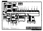
Page 123: ...U V W J501 NC NC 10 9 8 7 6 5 4 3 GND 12V GND PWR_SW 2 1 KEY_RXD A KEY_RXD B KEY_TXD A KEY_TXD B RCU 016 CONTROL UNIT 2 1 5 10 20 30m 9 XH10P W 5P A IEC 61162 2 HDG SENSOR 1 RS 232C CABLE PC IEC 61162...

Reviews: