1-12
Flush mounting
Use the optional flush mount kit FP03-09870 (Code No. 008-535-630) to flush mount the control
unit RCU-014, RCU-015 and/or RCU016 in a console.
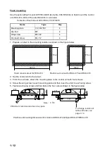
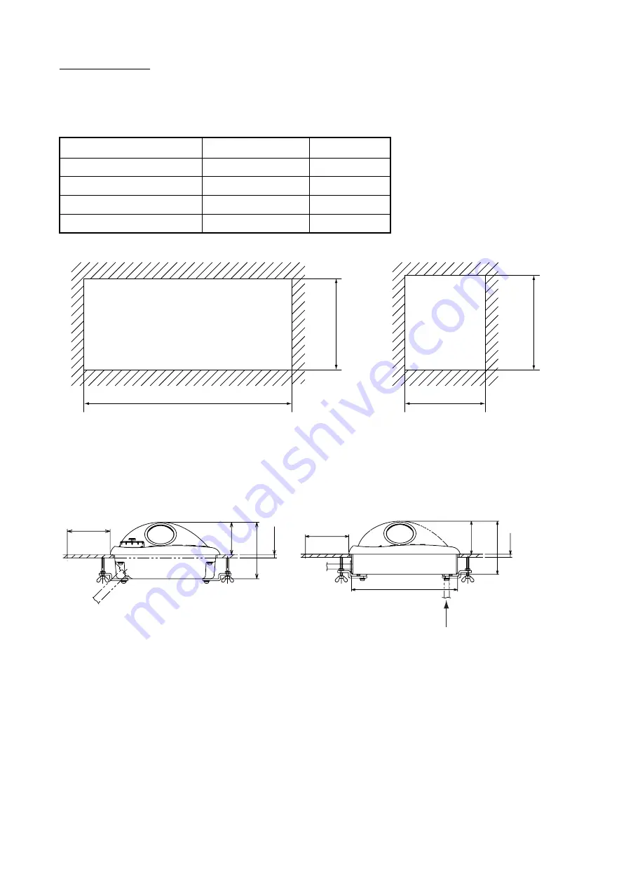
1. Prepare a cutout in the mounting location as shown in the figure below.
Flush mount cutout for RCU-014 Flush mount cutout for RCU-015 and RCU-016
2. Set the control unit to the cutout.
3. From the rear side, attach the mounting plate to the control unit with four screws.
4. Screw the wing screw to each mounting plate and then insert hex bolt to each wing screw.
5. Fasten each wing screw and then fasten the hex nuts as shown in the figure below.
Flush mount mounting dimensions for control unit RCU-014 (left) and RCU-015/RCU-016
Contents of flush mount kit for RCU-014/015/016
Name
Type
Qty
Mounting plate
03-163-7531
4
Hex bolt
M5
4
Wing screw
M5
×
40
4
Pan head screw
M4
×
12
4
388
150
±
2
170
±
2
176
±
2
±
2
(P)
#70
53
92
(P)
#70
171
53
86
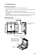
Note: P 10
<
=
# Minimum recommended service space
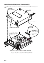
To change location of
cable entrance, see
page 1-14.
Summary of Contents for 2167DS-BB
Page 8: ...vi This page is intentionally left blank...
Page 56: ...3 14 This page intentionally left blank...
Page 91: ...14 Feb 2011 Y NISHIYAMA D 1...
Page 92: ...D 2...
Page 93: ...May 17 07 R Esumi D 3...
Page 94: ...1 Sep 2010 Y NISHIYAMA D 4...
Page 95: ...Takahashi T Y Hatai D 5...
Page 96: ...Jan 18 08 R Esumi D 6...
Page 97: ...Apr 23 07 R Esumi D 7...
Page 98: ...Apr 23 07 R Esumi D 8...
Page 99: ...Apr 23 07 R Esumi D 9...
Page 100: ...Apr 23 07 R Esumi D 10...
Page 101: ...Apr 23 07 R Esumi D 11...
Page 102: ...D 12...
Page 103: ...D 13...
Page 104: ...D 14...
Page 105: ...Y Hatai D 15...
Page 106: ...Y Hatai D 16...
Page 107: ...Y Hatai D 17...
Page 108: ...Y Hatai D 18...
Page 109: ...Apr 05 04 D 19...
Page 110: ......


