4-12
Note:
When two memory card interface units are connected via a network, change ID code for the
second unit.
1. Remove the cover and set the IP0 bit of the DIP switch S1 on the CARDCPU board (03P9333)
to ON.
2. Set INIT bit of S1 to ON and turn on the radar. Wait until CR2 starts blinking. DO NOT turn off
the power until CR2 starts blinking.
3. Turn off the power and set INIT bit to OFF.
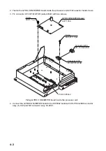
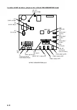
Memory card interface unit, showing location of DIP switch S1
Armored LAN cable kit
Type
Code No.
Contents
OP03-28900
000-082-658
Cable FR-FTPC-CY (10 m), Modular connector (2 pcs.)
OP03-28910
000-082-689
Cable FR-FTPC-CY (20 m), Modular connector. (2 pcs.)
OP03-28920
000-082-660
Cable FR-FTPC-CY (30 m), Modular connector (2 pcs.)
OFF
ON
(Default: all OFF)
IP0
IP1
IP2
INIT
J314
S1
CARDCPU board 03P9333
CR2
Summary of Contents for 2167DS-BB
Page 8: ...vi This page is intentionally left blank...
Page 56: ...3 14 This page intentionally left blank...
Page 91: ...14 Feb 2011 Y NISHIYAMA D 1...
Page 92: ...D 2...
Page 93: ...May 17 07 R Esumi D 3...
Page 94: ...1 Sep 2010 Y NISHIYAMA D 4...
Page 95: ...Takahashi T Y Hatai D 5...
Page 96: ...Jan 18 08 R Esumi D 6...
Page 97: ...Apr 23 07 R Esumi D 7...
Page 98: ...Apr 23 07 R Esumi D 8...
Page 99: ...Apr 23 07 R Esumi D 9...
Page 100: ...Apr 23 07 R Esumi D 10...
Page 101: ...Apr 23 07 R Esumi D 11...
Page 102: ...D 12...
Page 103: ...D 13...
Page 104: ...D 14...
Page 105: ...Y Hatai D 15...
Page 106: ...Y Hatai D 16...
Page 107: ...Y Hatai D 17...
Page 108: ...Y Hatai D 18...
Page 109: ...Apr 05 04 D 19...
Page 110: ......

