1-1
1. MOUNTING
1.1 Antenna Unit
Mounting considerations
The antenna unit is generally installed either on top of the wheelhouse, on the radar mast, or on
a suitable platform. The mounting location should afford a good all-round view and satisfy the
siting and mounting considerations mentioned below.
Siting
• No funnel, mast or derrick should be within the vertical beamwidth of the antenna unit in the bow
direction, especially zero degrees ±5
°
, to prevent blind sectors and false echoes on the radar
picture.
• Deposits and fumes from a funnel or other exhaust vent can adversely affect the aerial perfor-
mance and hot gases may deform the radiator. The antenna unit must not be mounted where
the temperature is more than 70
°
C.
• Locate a direction finder antenna clear of the antenna unit to prevent interference to the direc-
tion finder. A separation of more than two meters is recommended.
• Choose a location where reflections from the radar reflector will not be received by the radar
antenna.
• The "standard" antenna unit orientation has the cable glands directed toward the bow.
• Leave sufficient space around the unit for maintenance and servicing. See the antenna unit out-
line drawing for recommended maintenance space.
Mounting
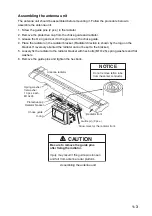
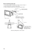
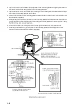
• Use rope and crane to hoist the antenna unit to the mounting location. Lifting fixtures are pro-
vided on the antenna chassis to which to fasten rope.
• Mount the unit parallel to the waterline.
• A hole is required in the mounting platform for the antenna cable.
• An appropriate platform should be constructed at the mounting location to facilitate installation
and maintenance work.
• Connect ground wire between antenna terminal on antenna chassis and ground point.
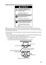
• If the mounting platform is made of steel paint it to prevent electrolytic corrosion. DO NOT paint
the antenna radiator.
NOTICE
Do not apply paint, anti-corrosive sealant
or contact spray to coating or plastic
parts of the equipment.
Those items contain organic solvents that
can damage coating and plastic parts,
especially plastic connectors.
Summary of Contents for 2167DS-BB
Page 8: ...vi This page is intentionally left blank...
Page 56: ...3 14 This page intentionally left blank...
Page 91: ...14 Feb 2011 Y NISHIYAMA D 1...
Page 92: ...D 2...
Page 93: ...May 17 07 R Esumi D 3...
Page 94: ...1 Sep 2010 Y NISHIYAMA D 4...
Page 95: ...Takahashi T Y Hatai D 5...
Page 96: ...Jan 18 08 R Esumi D 6...
Page 97: ...Apr 23 07 R Esumi D 7...
Page 98: ...Apr 23 07 R Esumi D 8...
Page 99: ...Apr 23 07 R Esumi D 9...
Page 100: ...Apr 23 07 R Esumi D 10...
Page 101: ...Apr 23 07 R Esumi D 11...
Page 102: ...D 12...
Page 103: ...D 13...
Page 104: ...D 14...
Page 105: ...Y Hatai D 15...
Page 106: ...Y Hatai D 16...
Page 107: ...Y Hatai D 17...
Page 108: ...Y Hatai D 18...
Page 109: ...Apr 05 04 D 19...
Page 110: ......

