


7
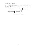
1.3.3 PWR Board (06P0242)
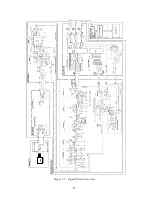
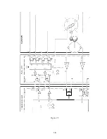
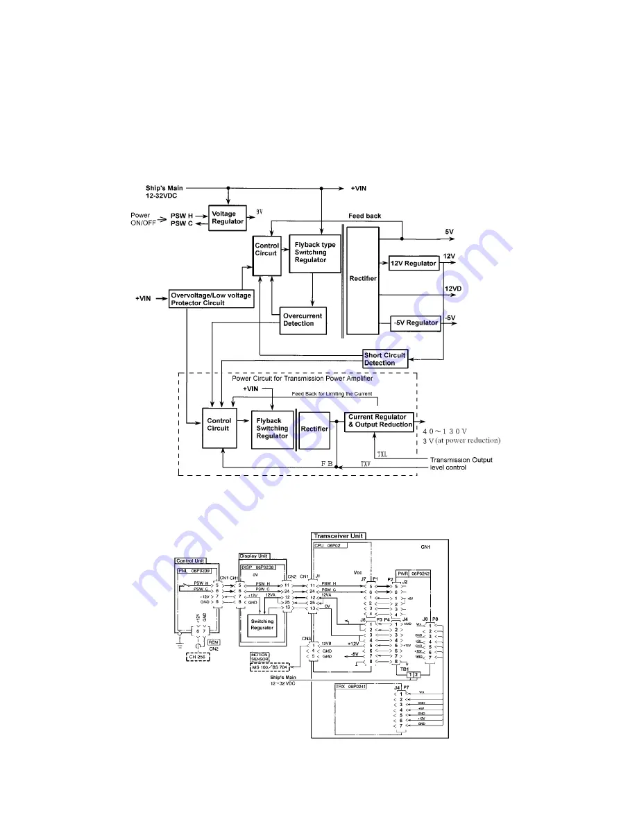
Figure 1.6 shows the block diagram of PWR board.
The power on/off switch in the control unit generates PSW-H and PSW-L signals to send them
to PWR board via the display unit. The PWR board generates 5V, -5V, 12V 12VD, and +B
voltage (VTX).
The 12VD voltage (12VA) is supplied to the display unit via CPU board. The VTX voltage is
determined with TXV voltage from CPU board.
VTX
Figure 1.4 Function diagram of the PWR Board (06P0242)
58
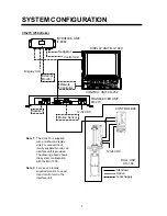
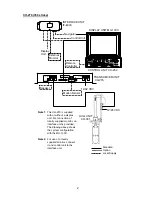
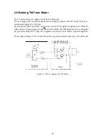
Figure 1.5 Shows power supply lines in the system.
Summary of Contents for CH-270
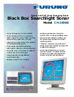
Page 1: ...COLOR SEARCHLIGHT SONAR CH 270...
Page 13: ...10 58 59 6 6 DRV 06P0154 Hull Unit XDR Slip ring Figure 2 1 Signal Flow in Transmitter...
Page 14: ...11 Hull unit XDR Slip ring 6 6 59 58 Figure 2 2 Signal Flow in Receiver...
Page 19: ...16 Figure 2 5 TRANSCEIVER UNIT CPU J2 3 4 3 4 5 6 J10 5 6 7 8 CR16 U17 U34 191 R104 R105...
Page 23: ...20 DRV Board 06P0154...
Page 54: ......
Page 55: ......
Page 64: ......
Page 65: ......
Page 66: ......
Page 67: ......
Page 68: ......
Page 69: ......
Page 70: ......
Page 71: ......
Page 72: ......
Page 73: ......
Page 74: ......
Page 75: ......
Page 76: ......
Page 77: ......
Page 78: ......
Page 79: ......
Page 80: ......
Page 81: ......
Page 82: ......
Page 83: ......
Page 84: ......
Page 85: ......
Page 86: ......
Page 87: ......
Page 88: ......