


12
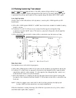
2.3 Raising/Lowering Transducer
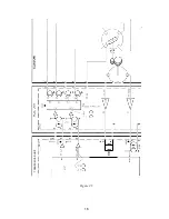
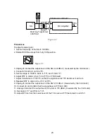
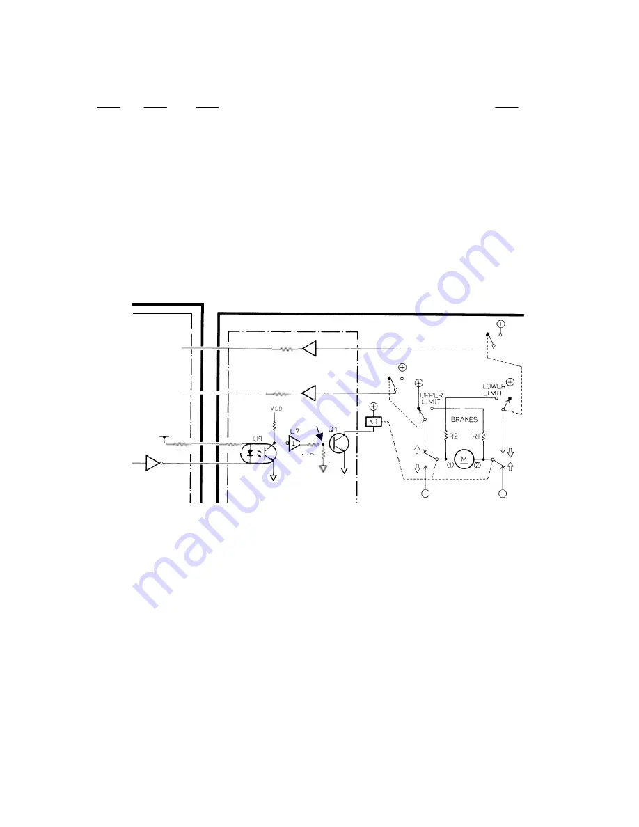
See the simplified circuit diagram below. The CPU generates rising and lower control signals,
UPC and DNC. The DNC signal is generated when the down key is pressed and the UPC signal
is generated when the up key is pressed. These signals change the status of R/L CONT signal.
Lowering Operation
The DC motor in the hull unit lowers the transducer, receiving R/L CONT signal from CPU
board below.
1) When R/L CONT signal is HIGH, U9 on DRV board is led into conductive condition, causing
that K1 activates.
2) Terminals
①
and
②
of the motor are connected to the negative and positive lines
respectively to power the DC motor. The motor is connected to the positive line through the
lower limit switch.
3) When the lower limit switch K3 is kicked, R2 is connected across the motor as a brake.
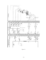
Hull unit
DRV board
CPU board
LOWER
J10
#3
#1
J2
#1
#2
R/L Cont
Signal
RAISE
Figure 2.3 Raise/Lower Circuit
Raise Operation
The transducer raises in the following sequence.
1) When R/L CONT signal is LOW, U9 is led into cut off condition, causing that K1 inactivates.
2) Terminal
①
of the motor is connected to the positive line through the relay contact and the
upper limit switch S2, while terminal
②
to the negative line through the relay contact. As a
result, the motor rotates to raise the transducer.
3) When the transducer is completely hoisted up, the upper limit switch is kicked, causing that
the positive line is disconnected from terminal
①
and a brake resistor R1 is connected across
the motor.
NOTE: When the display unit is turned off, the R/L level being fed from the display unit
becomes LOW, and raise operation is executed automatically.
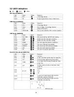
While the transducer is raising (lowering), the LED above up (down) arrow key on the control
unit blinks and it lights when completed.
#1
J2
L: Raise
H: Lower
Summary of Contents for CH-270
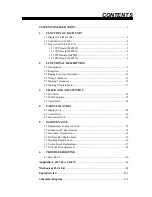
Page 1: ...COLOR SEARCHLIGHT SONAR CH 270...
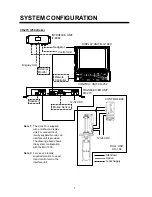
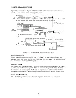
Page 13: ...10 58 59 6 6 DRV 06P0154 Hull Unit XDR Slip ring Figure 2 1 Signal Flow in Transmitter...
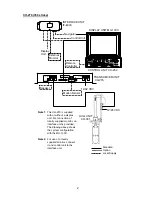
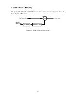
Page 14: ...11 Hull unit XDR Slip ring 6 6 59 58 Figure 2 2 Signal Flow in Receiver...
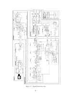
Page 19: ...16 Figure 2 5 TRANSCEIVER UNIT CPU J2 3 4 3 4 5 6 J10 5 6 7 8 CR16 U17 U34 191 R104 R105...
Page 23: ...20 DRV Board 06P0154...
Page 54: ......
Page 55: ......
Page 64: ......
Page 65: ......
Page 66: ......
Page 67: ......
Page 68: ......
Page 69: ......
Page 70: ......
Page 71: ......
Page 72: ......
Page 73: ......
Page 74: ......
Page 75: ......
Page 76: ......
Page 77: ......
Page 78: ......
Page 79: ......
Page 80: ......
Page 81: ......
Page 82: ......
Page 83: ......
Page 84: ......
Page 85: ......
Page 86: ......
Page 87: ......
Page 88: ......


