


15
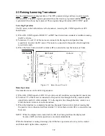
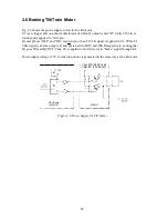
2.5 Training Transducer
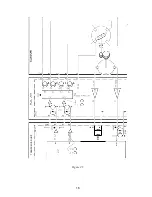
Basically the circuit is the same as the tilt control circuit. See the simplified circuit diagram on
the next page.
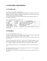
The phased pulse generator U5 drives the train motor with TR CLK (TRM1) and TR CW/CCW
(TRM2) signals from CPU board.
A slit on the rotary disc generates a “Heading” signal (TR FORE) when the transducer faces
toward the bow. The TR FORE signal is sent to the CPU as TR 0°. At every power-on, the CPU
searches TR 0° signal. If the CPU does not detect TR 0° signal, error manage TRAIN NG
appears.
The transducer rotates in either “normal” or “fast” mode. In the normal mode, transmission and
reception are made while the transducer is rotating in 6° steps. In the fast mode, the transducer
moves in 12° steps after transmission and reception are completed.
Summary of Contents for CH-270
Page 1: ...COLOR SEARCHLIGHT SONAR CH 270...
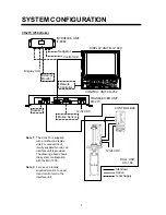
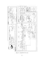
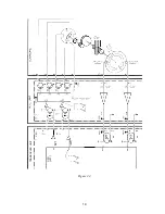
Page 13: ...10 58 59 6 6 DRV 06P0154 Hull Unit XDR Slip ring Figure 2 1 Signal Flow in Transmitter...
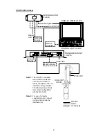
Page 14: ...11 Hull unit XDR Slip ring 6 6 59 58 Figure 2 2 Signal Flow in Receiver...
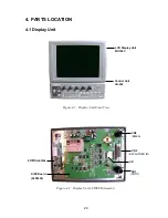
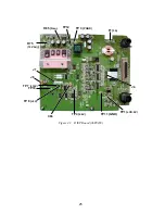
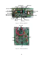
Page 19: ...16 Figure 2 5 TRANSCEIVER UNIT CPU J2 3 4 3 4 5 6 J10 5 6 7 8 CR16 U17 U34 191 R104 R105...
Page 23: ...20 DRV Board 06P0154...
Page 54: ......
Page 55: ......
Page 64: ......
Page 65: ......
Page 66: ......
Page 67: ......
Page 68: ......
Page 69: ......
Page 70: ......
Page 71: ......
Page 72: ......
Page 73: ......
Page 74: ......
Page 75: ......
Page 76: ......
Page 77: ......
Page 78: ......
Page 79: ......
Page 80: ......
Page 81: ......
Page 82: ......
Page 83: ......
Page 84: ......
Page 85: ......
Page 86: ......
Page 87: ......
Page 88: ......


