


19
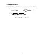
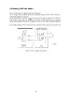
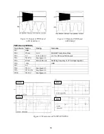
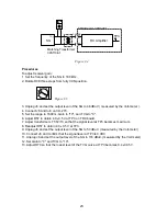
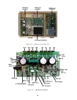
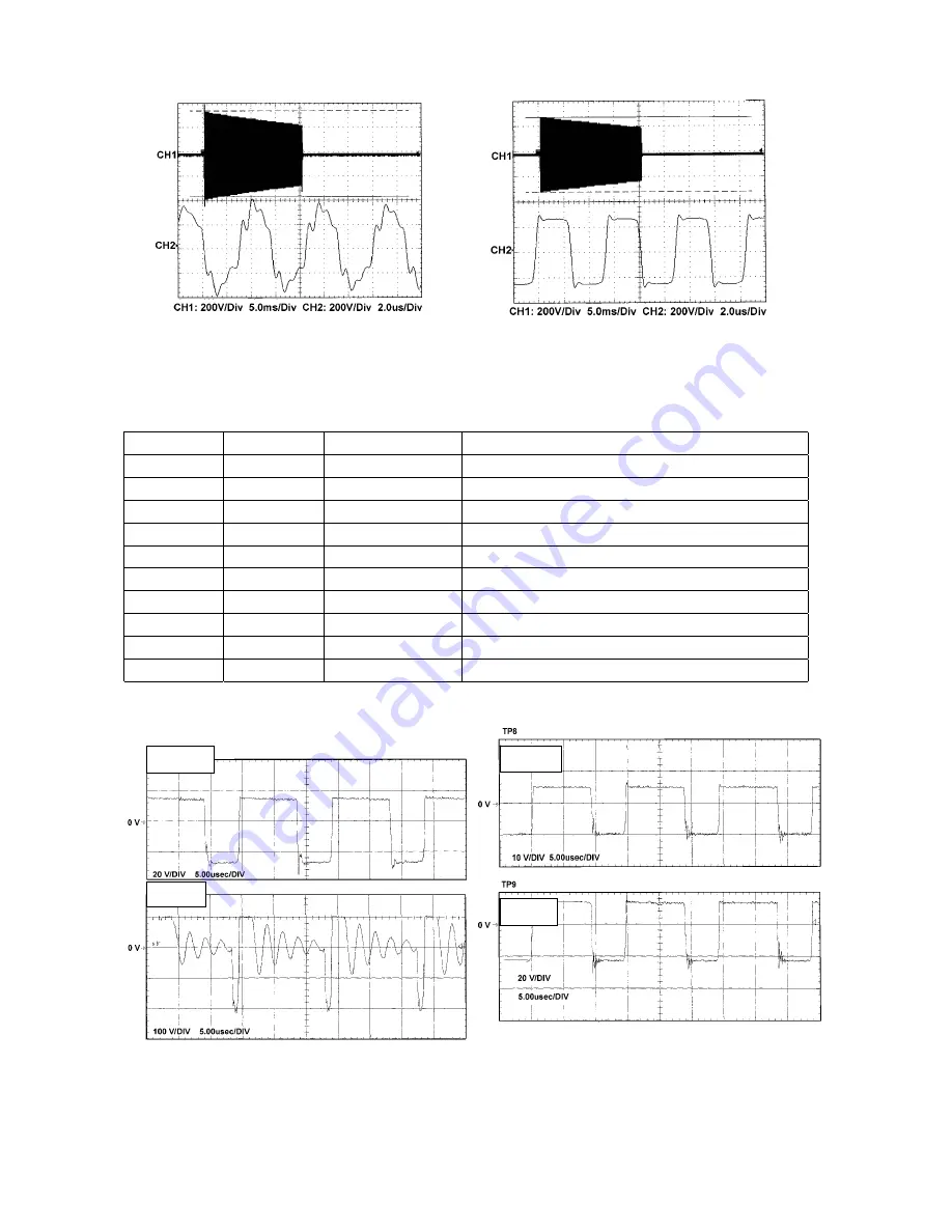
Figure 3.1 Output of TRX board
Figure 3.2 Output of TRX board
(with transducer)
(with dummy)
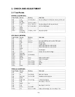
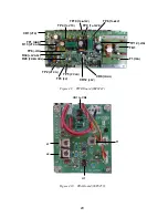
PWR Board (06P0242)
Test Points Name
Rating
Remarks
TP1 GND
TP2
VTX-G
0.9 V
MOS FET Gate Drive Clock
TP3
5 V
4.75 to 5.25 V
+5 V for CPU and TRX boards
TP4
TO VTX
See figure 3.3
TP5
P CLK
68.0 ±0.05 kHz
Switching frequency of VTX voltage regulator
TP6 -VIN
GND
TP7 0
V
TP8
TO 5 V
See figure 3.3
TP9
TO 12 VD
See figure 3.3
TP10
TO 12 V
See figure 3.3
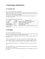
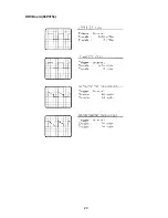
Figure 3.3 Waveforms at TP4/TP8/TP9/TP10
TP10
TP8
TP4
TP9
Summary of Contents for CH-270
Page 1: ...COLOR SEARCHLIGHT SONAR CH 270...
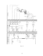
Page 13: ...10 58 59 6 6 DRV 06P0154 Hull Unit XDR Slip ring Figure 2 1 Signal Flow in Transmitter...
Page 14: ...11 Hull unit XDR Slip ring 6 6 59 58 Figure 2 2 Signal Flow in Receiver...
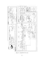
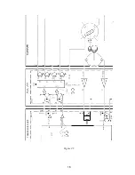
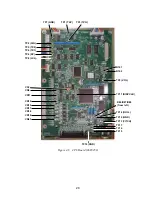
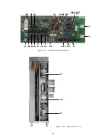
Page 19: ...16 Figure 2 5 TRANSCEIVER UNIT CPU J2 3 4 3 4 5 6 J10 5 6 7 8 CR16 U17 U34 191 R104 R105...
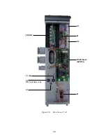
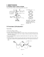
Page 23: ...20 DRV Board 06P0154...
Page 54: ......
Page 55: ......
Page 64: ......
Page 65: ......
Page 66: ......
Page 67: ......
Page 68: ......
Page 69: ......
Page 70: ......
Page 71: ......
Page 72: ......
Page 73: ......
Page 74: ......
Page 75: ......
Page 76: ......
Page 77: ......
Page 78: ......
Page 79: ......
Page 80: ......
Page 81: ......
Page 82: ......
Page 83: ......
Page 84: ......
Page 85: ......
Page 86: ......
Page 87: ......
Page 88: ......


