
35
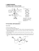
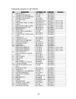
5.4 Tilt Gear Box Replacement
Disassembling
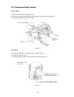
1) Loosen 8 screws and take off the soundome (U). To detach the soundome from the main
body, use (-) screwdrivers in the same way as they have been used to remove the soundome
(D). See Fig. 5.2.
2) Unplug P1.
3) Remove the gear box cover by loosening four screws.
4) Loosen four socket-head bolts and disengage the rack gear from the tilt shaft by lifting the
gear box.
Figure 5.6
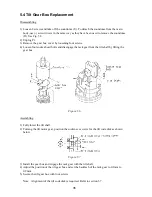
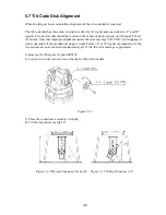
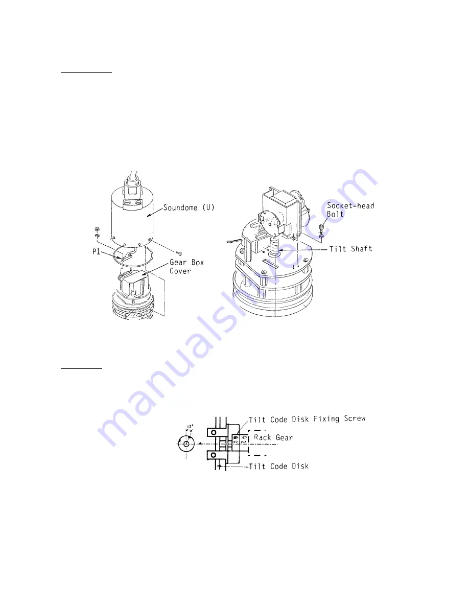
Assembling
1) Fully lower the tilt shaft.
2) Turning the tilt motor gear, position the socket-see screws for the tilt code disk as shown
below.
Figure 5.7
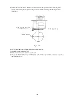
3) Install the gear box and engage the rack gear with the tilt shaft.
4) Adjust the position of the tilt gear box and set the backlash of the rack gear to 0.1mm to
0.2mm.
5) Secure the tilt gear box with four screws.
Note: Alignment of the tilt code disk is required. Refer to section 5.7.
Summary of Contents for CH-270
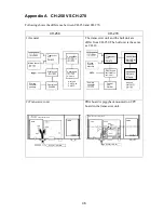
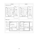
Page 1: ...COLOR SEARCHLIGHT SONAR CH 270...
Page 13: ...10 58 59 6 6 DRV 06P0154 Hull Unit XDR Slip ring Figure 2 1 Signal Flow in Transmitter...
Page 14: ...11 Hull unit XDR Slip ring 6 6 59 58 Figure 2 2 Signal Flow in Receiver...
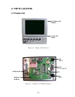
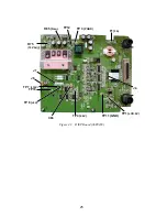
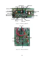
Page 19: ...16 Figure 2 5 TRANSCEIVER UNIT CPU J2 3 4 3 4 5 6 J10 5 6 7 8 CR16 U17 U34 191 R104 R105...
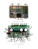
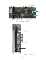
Page 23: ...20 DRV Board 06P0154...
Page 54: ......
Page 55: ......
Page 64: ......
Page 65: ......
Page 66: ......
Page 67: ......
Page 68: ......
Page 69: ......
Page 70: ......
Page 71: ......
Page 72: ......
Page 73: ......
Page 74: ......
Page 75: ......
Page 76: ......
Page 77: ......
Page 78: ......
Page 79: ......
Page 80: ......
Page 81: ......
Page 82: ......
Page 83: ......
Page 84: ......
Page 85: ......
Page 86: ......
Page 87: ......
Page 88: ......


