
37
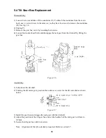
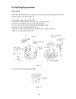
Assembling
1) Clean the slip-ring surface with alchol.
2) Pass the slip-ring assembly through the train shaft and install so that it may be in contact with
the base of the train shaft.
3) Solder leads of the slip-ring and apply silicone rubber over them.
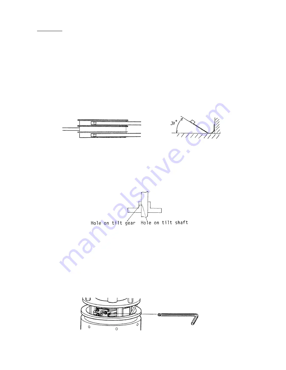
4) Loosen the carbon brush fixing screws and install the carbon brush assembly.
5) Tighten the carbon brush fixing screws so that the brushes contact the center part of the
slip-rings as shown below.
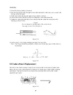
Caution
Do not change the bending angle of the carbon brush.
The angle is set to 30° at the factory.
Figure 5.10
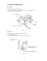
6) Follow steps 1) to 6) of disassembling procedure in reverse order.
Note: The tilt gear should be positioned so that its screw holes may agree with the holes on
the tilt shaft.
Figure 5.11
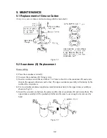
5.6 Carbon Brush Replacement
When the carbon brush assembly is replaced, use the procedure for the slip-ring replacement.
When only one or two carbon brushes are replaced, it is unnecessary to disassemble soundome
mechanisms. Unsolder the lead wire and loosen the socket head bolt with the ball wrench
supplied as spare parts.
Figure 5.12
Summary of Contents for CH-270
Page 1: ...COLOR SEARCHLIGHT SONAR CH 270...
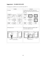
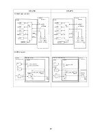
Page 13: ...10 58 59 6 6 DRV 06P0154 Hull Unit XDR Slip ring Figure 2 1 Signal Flow in Transmitter...
Page 14: ...11 Hull unit XDR Slip ring 6 6 59 58 Figure 2 2 Signal Flow in Receiver...
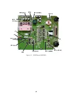
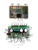
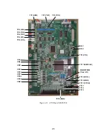
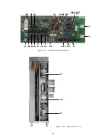
Page 19: ...16 Figure 2 5 TRANSCEIVER UNIT CPU J2 3 4 3 4 5 6 J10 5 6 7 8 CR16 U17 U34 191 R104 R105...
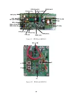
Page 23: ...20 DRV Board 06P0154...
Page 54: ......
Page 55: ......
Page 64: ......
Page 65: ......
Page 66: ......
Page 67: ......
Page 68: ......
Page 69: ......
Page 70: ......
Page 71: ......
Page 72: ......
Page 73: ......
Page 74: ......
Page 75: ......
Page 76: ......
Page 77: ......
Page 78: ......
Page 79: ......
Page 80: ......
Page 81: ......
Page 82: ......
Page 83: ......
Page 84: ......
Page 85: ......
Page 86: ......
Page 87: ......
Page 88: ......


