
39
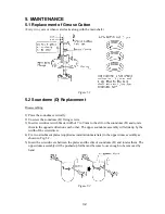
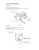
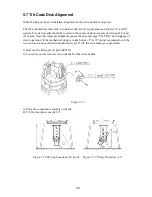
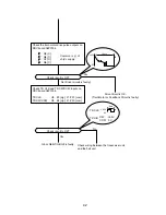
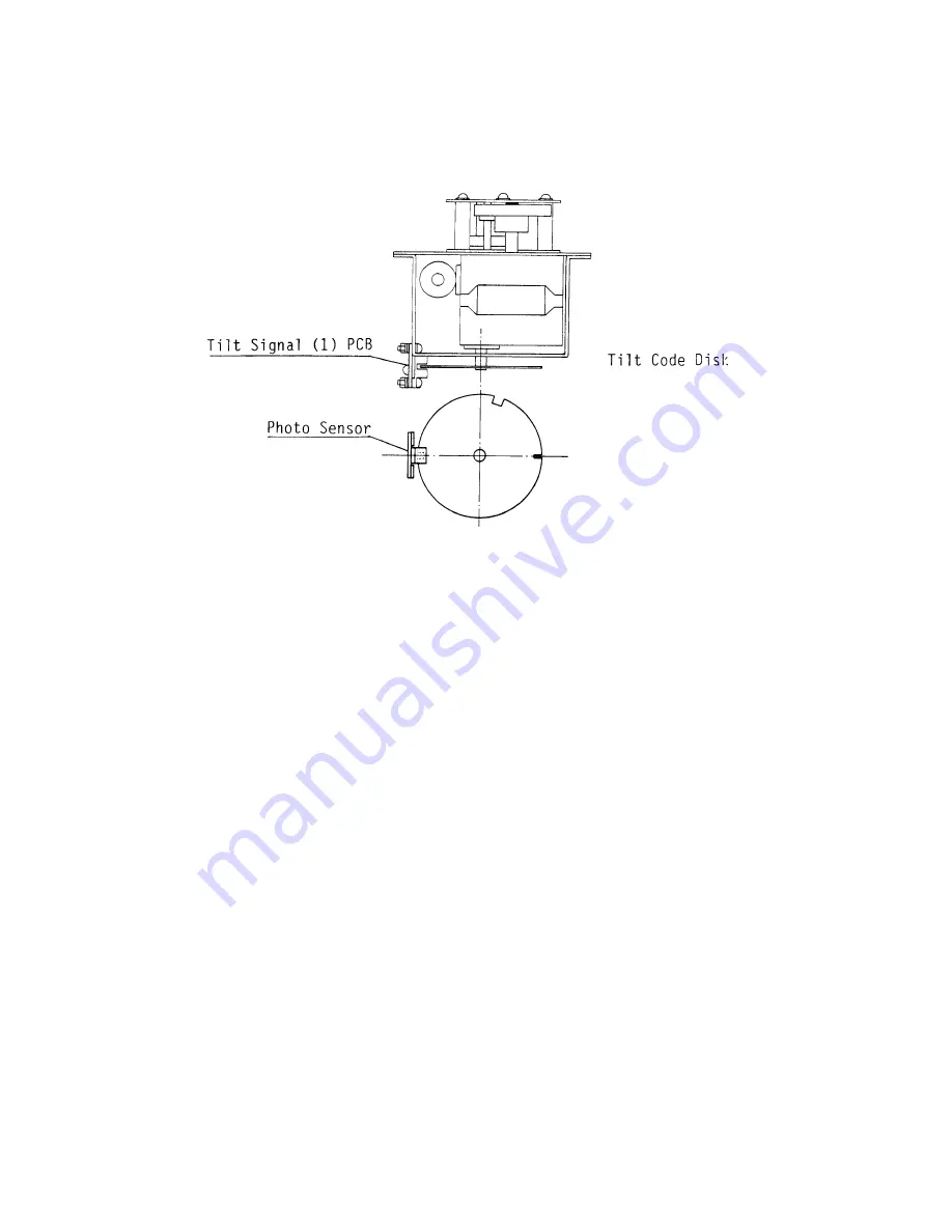
5) Rotate the tilt code disk so that the second narrowest slit is placed in the center of photo
sensor on the tilt signal (1) pcb. See Fig.5.16. Be careful not change the tilt angle of the
transducer.
Figure 5.16
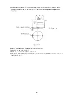
6) Fix the tilt code disk by tightening the socket set screws.
7) Reinstall the tilt signal (2) pcb.
8) Make all interconnections between the units.
9) Check that LEDs CR8 (+8°) and CR9 (93°) on the tilt driver pcb blinks simultaneously when
the tilt angle is 30°.
Summary of Contents for CH-270
Page 1: ...COLOR SEARCHLIGHT SONAR CH 270...
Page 13: ...10 58 59 6 6 DRV 06P0154 Hull Unit XDR Slip ring Figure 2 1 Signal Flow in Transmitter...
Page 14: ...11 Hull unit XDR Slip ring 6 6 59 58 Figure 2 2 Signal Flow in Receiver...
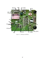
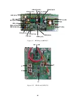
Page 19: ...16 Figure 2 5 TRANSCEIVER UNIT CPU J2 3 4 3 4 5 6 J10 5 6 7 8 CR16 U17 U34 191 R104 R105...
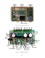
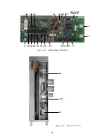
Page 23: ...20 DRV Board 06P0154...
Page 54: ......
Page 55: ......
Page 64: ......
Page 65: ......
Page 66: ......
Page 67: ......
Page 68: ......
Page 69: ......
Page 70: ......
Page 71: ......
Page 72: ......
Page 73: ......
Page 74: ......
Page 75: ......
Page 76: ......
Page 77: ......
Page 78: ......
Page 79: ......
Page 80: ......
Page 81: ......
Page 82: ......
Page 83: ......
Page 84: ......
Page 85: ......
Page 86: ......
Page 87: ......
Page 88: ......


