
40
6. TROUBLESHOOTING
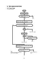
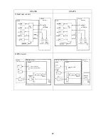
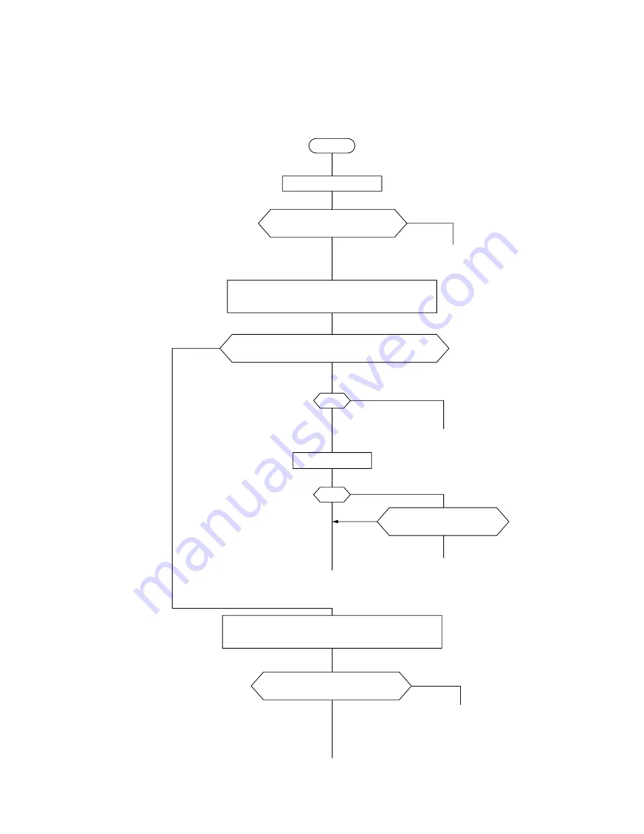
6.1 Flow Chart
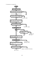
1) Train/Tilt Check
START
Conduct self-check.
Conduct results of train/
tilt motor is OK?
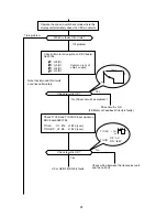
Measure the supply voltage between J1 #1(+)
and #2(-) on PWR board 06P0147.
10.8V to 15.6V for 12VDC set and
21.6V to 31.2V for 24VDC set?
No
Yes
END
No
No
Check ship’s supply.
No
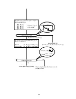
Problem is cleared with
new fuse?
Yes
Yes
END
Check switch S1.
No
Yes
Yes
0V?
OK?
Measure the voltage at collector of Q5 on PWR
board 06P0147.
Check fuse F2.
+8V for 12VDC set and +20V
for 24VDC set?
Note:
Measure the voltage with the train
and tilt motors stopped.
Yes
No
Q5/U1 on 06P0147 is
faulty.
Summary of Contents for CH-270
Page 1: ...COLOR SEARCHLIGHT SONAR CH 270...
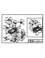
Page 13: ...10 58 59 6 6 DRV 06P0154 Hull Unit XDR Slip ring Figure 2 1 Signal Flow in Transmitter...
Page 14: ...11 Hull unit XDR Slip ring 6 6 59 58 Figure 2 2 Signal Flow in Receiver...
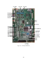
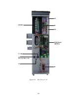
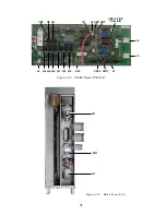
Page 19: ...16 Figure 2 5 TRANSCEIVER UNIT CPU J2 3 4 3 4 5 6 J10 5 6 7 8 CR16 U17 U34 191 R104 R105...
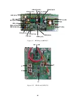
Page 23: ...20 DRV Board 06P0154...
Page 54: ......
Page 55: ......
Page 64: ......
Page 65: ......
Page 66: ......
Page 67: ......
Page 68: ......
Page 69: ......
Page 70: ......
Page 71: ......
Page 72: ......
Page 73: ......
Page 74: ......
Page 75: ......
Page 76: ......
Page 77: ......
Page 78: ......
Page 79: ......
Page 80: ......
Page 81: ......
Page 82: ......
Page 83: ......
Page 84: ......
Page 85: ......
Page 86: ......
Page 87: ......
Page 88: ......


