


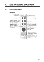


1. OPERATIONAL OVERVIEW
1-3
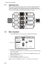
1.2
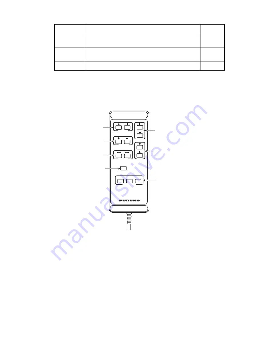
Remote Controller
The Remote Controller CH-343 enables control of the processor unit from a remote
location.
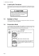
1.3
Turning the Power On/Off
Power on
Press the [PWR] switch on the main panel. The lamp above the switch lights to show
that power is turned on.
Power off
With the ship speed under 15 knots, retract the transducer with the [
] key on the main
panel. The lamp above the key lights while the transducer is being raised and goes off
when the transducer fully raised. Then press the [PWR] switch.
Note:
The transducer is automatically retracted into the tank even if the [PWR] switch
is pressed before retracting the transducer. However, for safety purpose, make it a
habit to retract the transducer before turning off the power.
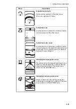
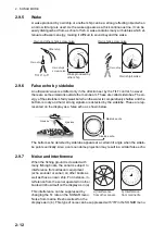
V:H RANGE
Changes the horizontal range scale in the vertical fan
mode.
3.3
AUTO
TRAIN
Changes the auto and manual train in the vertical fan
mode.
3.4
MENU
Displays the menu screen of the mode in use.
Key
Description
Remark
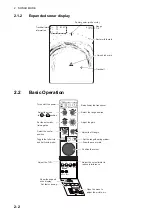
C H - 3 4 3
C H - 3 4 3
REMOTE CONTROL
RAISE/
LOWER
MODE
TRAIN
TILT
RANGE
CUSTOM MODE
1 2 3
FULL/HALF
DISPLAY RANGE
Selects Range.
Raise/lower the
transducer.
Select display
mode.
Select fishing
ground.
Tilt angle control/
Select center of
rotation in vertical
scanning.
Select center of
vertical fan mode/
direction of scanning.
Selects the width on
the transducer
training sector.
Summary of Contents for CH-37BB
Page 1: ...COLOR SECTOR SCANNING SONAR CH 37BB OPERATOR S MANUAL www furuno com Model ...
Page 10: ...SYSTEM CONFIGURATION viii This page is intentionally left blank ...
Page 40: ...3 VERTICAL FAN MODE 3 12 This page is intentionally left blank ...
Page 44: ...4 3D MODE 4 4 This page is intentionally left blank ...
Page 48: ...5 PRESENTATION MODE 5 4 This page is intentionally left blank ...
Page 52: ...6 CUSTOM MODE KEYS 6 4 This page is intentionally left blank ...
Page 58: ...7 SYSTEM MENU 7 6 This page is intentionally left blank ...
Page 66: ...8 MAINTENANCE 8 8 This page is intentionally left blank ...


