

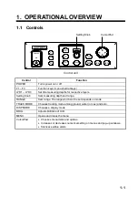

1. OPERATIONAL OVERVIEW
1-5
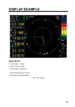
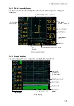
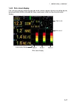
1.4.2 Ship’s
speed
display
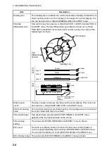
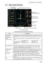
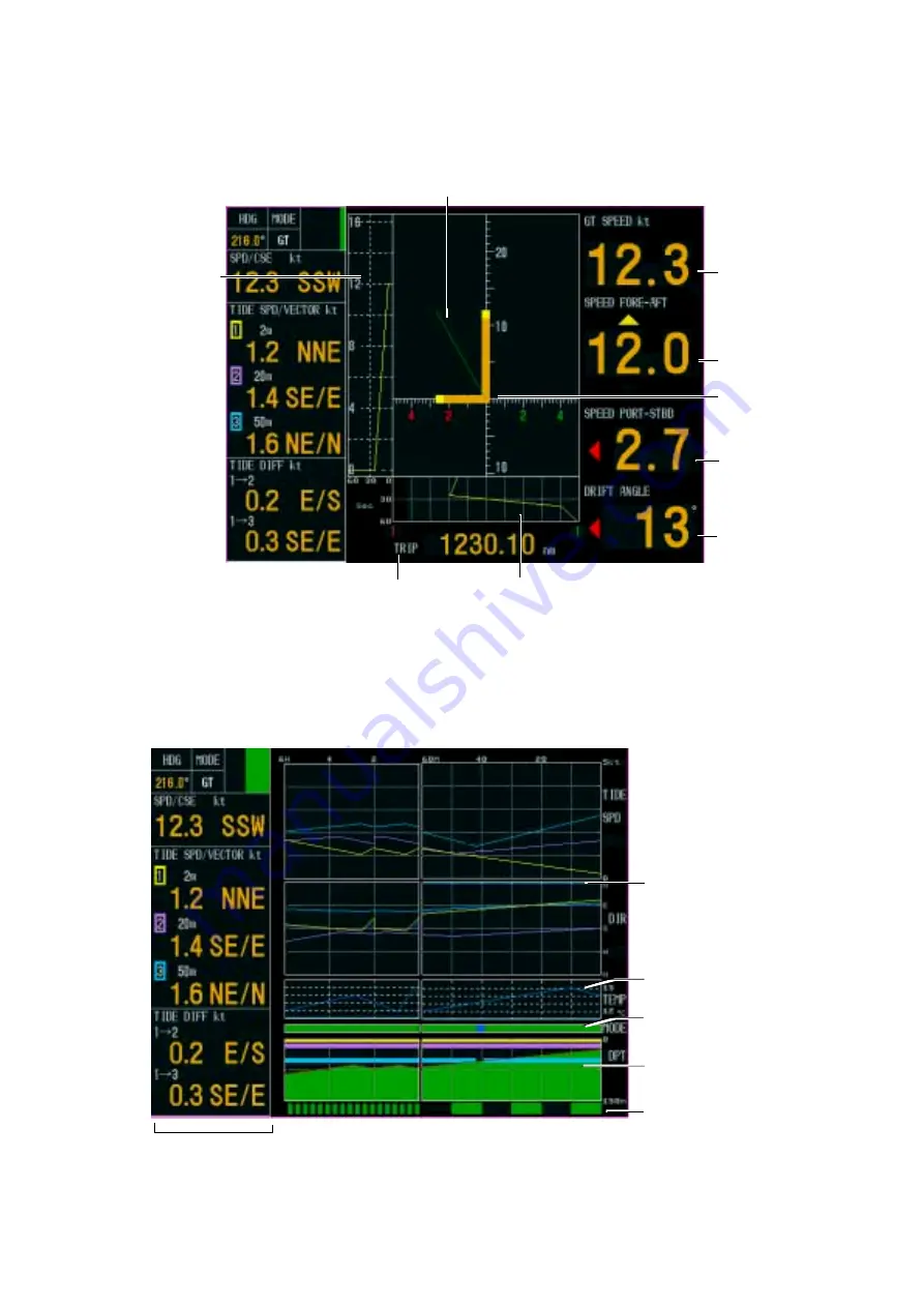
The ship’s speed display shows ship’s fore-aft and port-starboard speeds in analog and
digital form.
Trip
Distance
Ship Speed
(Synthesized Speed)
Fore-Aft Speed
History Graph
Port-Starboard Speed History Graph
Fore-Aft Speed
Port-Starboard
Speed
Drift Angle
Own Ship Vector
Synthesized Speed Vector (Green)
Ship’s speed display
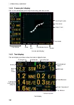
1.4.3 Graph
display
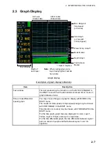
The graph display plots water temperature and depth data in graph form.
*: Sensor required.
Text Window
Depth Graph
Mode Marker
Water Temp. Graph*
Tide Graph
(or Tide Diff
or Ship Speed)
Trip Distance
Marker
Graph display
Summary of Contents for CI-68
Page 1: ...DOPPLER SONAR CURRENT INDICATOR CI 68 ...
Page 10: ......


