


2. MOUNTING
2-4
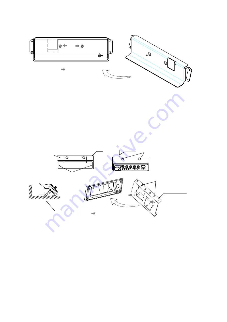
Using the FP66-00601
1. Fasten the bracket to the control unit, using two pan head screws (M4x10).
: Pan head screws
Bracket
2. Fasten the bracket to the mounting location with four 4x16 tapping screws.
Using the FP06-01120
1. Fasten the mounting plate to the mounting location with two 5x20 tapping screws.
2. Fix the bracket to the control unit with two hex. screws (M4x12).
3. Insert screwdriver from the top of the mounting plate holes and then loosely fasten two
hex. screws (M4x12).
Cable entrance hole
Cable can be passed this direction.
Mounting plate
Bracket
Tapping screws (5X20)
Cable
Fasten the screws
to fix the bracket.
Bracket
: Fix with hex. screws.
Set to the hex. screws
tightened at step 3.
Mounting the control unit
4. Attach the control unit to the mounting plate and then tightly fasten two hex. screws.
5. Attach two hole plugs to the holes at the top of the mounting plate.
Summary of Contents for CI-88
Page 4: ...ii SYSTEM CONFIGURATIONS System configuration ...
Page 24: ...2 MOUNTING 2 14 This page is intentionally left blank ...
Page 34: ...3 WIRING 3 10 This page is intentionally left blank ...
Page 53: ...4 ADJUSTMENT 4 19 ...
Page 55: ...4 ADJUSTMENT 4 21 ...
Page 56: ...4 ADJUSTMENT 4 22 This page is intentionally left blank ...
Page 63: ...Takahashi T Y Hatai D 1 ...
Page 64: ...Y Hatai D 2 ...
Page 65: ...Y Hatai D 3 ...
Page 66: ...22 Mar 2011 Y NISHIYAMA D 4 ...
Page 67: ...Takahashi T Y Hatai D 5 ...
Page 68: ...D 6 19 Mar 2015 H MAKI ...
Page 69: ...Takahashi T Y Hatai D 7 ...
Page 70: ...D 8 ...
Page 71: ...Dec 19 03 D 9 ...
Page 72: ...D 10 ...
Page 73: ...Dec 19 03 D 11 ...
Page 74: ...D 12 ...
Page 75: ...Feb 22 05 D 13 ...
Page 76: ...Feb 22 05 D 14 ...
Page 77: ...Feb 22 05 D 15 ...
Page 78: ...Feb 22 05 D 16 ...
Page 79: ...Nov 15 05 D 17 ...
Page 80: ...29 May 2014 H MAKI D 18 ...
Page 81: ...D 19 ...
Page 82: ...D 20 Nov 27 03 ...


