


2. MOUNTING
2-8
2.2 Transceiver
Unit
Mounting considerations
•
Since the transceiver unit generates heat, install it in a dry, well-ventilated place. The
cooling fans at the top of the unit must not be obstructed, to allow heat to escape.
•
This unit is designed for bulkhead mounting to permit dissipation of heat. If bulkhead
mounting is absolutely impossible, mount the unit on the floor leaving at least 50 mm
clearance between it and the floor to permit dissipation of heat.
•
This unit weights 12 kg. Reinforce the mounting area, if necessary.
•
Leave space around the unit for maintenance and checking. Refer to the drawing at the
back of this manual.
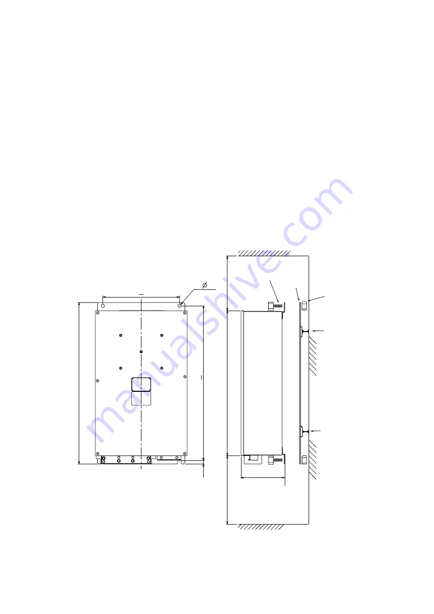
Mounting procedure
1. Weld the steel plate (shipyard supply) with four mounting holes to the bulkhead.
2. Use four bolts and nuts (M10, supplied as installation material) to fix the transceiver unit
to the steel plate described at step 1.
4- 12
12
566 + 0.5
160
#250
530
#200
590
280 + 0.5
Bolt
Nut
Welding
Welding
Steel
plate
Transceiver unit, mounting dimensions (mm)
Summary of Contents for CI-88
Page 4: ...ii SYSTEM CONFIGURATIONS System configuration ...
Page 24: ...2 MOUNTING 2 14 This page is intentionally left blank ...
Page 34: ...3 WIRING 3 10 This page is intentionally left blank ...
Page 53: ...4 ADJUSTMENT 4 19 ...
Page 55: ...4 ADJUSTMENT 4 21 ...
Page 56: ...4 ADJUSTMENT 4 22 This page is intentionally left blank ...
Page 63: ...Takahashi T Y Hatai D 1 ...
Page 64: ...Y Hatai D 2 ...
Page 65: ...Y Hatai D 3 ...
Page 66: ...22 Mar 2011 Y NISHIYAMA D 4 ...
Page 67: ...Takahashi T Y Hatai D 5 ...
Page 68: ...D 6 19 Mar 2015 H MAKI ...
Page 69: ...Takahashi T Y Hatai D 7 ...
Page 70: ...D 8 ...
Page 71: ...Dec 19 03 D 9 ...
Page 72: ...D 10 ...
Page 73: ...Dec 19 03 D 11 ...
Page 74: ...D 12 ...
Page 75: ...Feb 22 05 D 13 ...
Page 76: ...Feb 22 05 D 14 ...
Page 77: ...Feb 22 05 D 15 ...
Page 78: ...Feb 22 05 D 16 ...
Page 79: ...Nov 15 05 D 17 ...
Page 80: ...29 May 2014 H MAKI D 18 ...
Page 81: ...D 19 ...
Page 82: ...D 20 Nov 27 03 ...


