


4. ADJUSTMENT
4-13
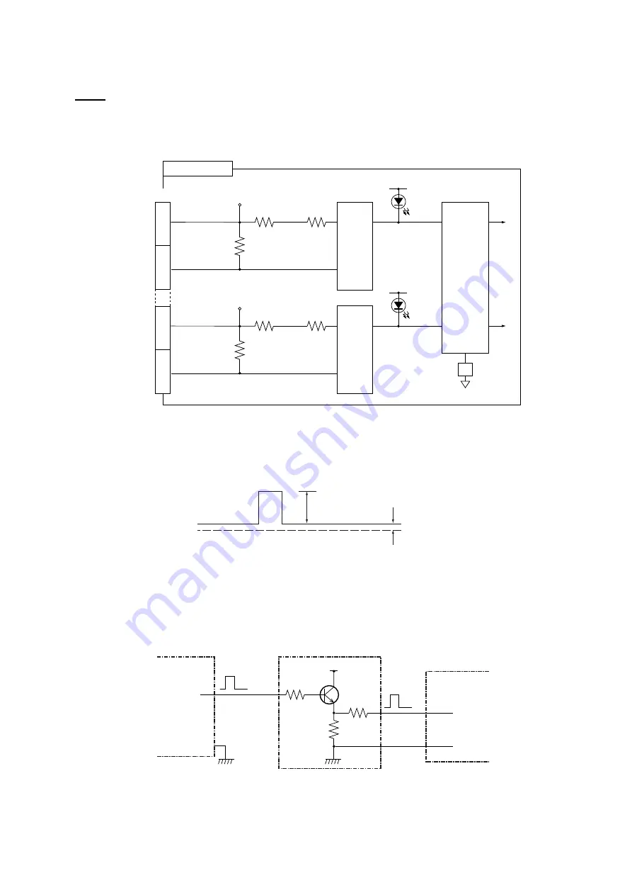
4.3.2 Suppressing
interference
Input
Up to two interfering equipment can be connected to the interference rejection circuit in the
transceiver unit via EX KP IN 1 or EX KP IN 2 port. This circuit receives the keying pulse
(KP) from the interfering equipment to reject interference.
H
C
TP2
TB-4
EKP1
EKP2
9
16
CR14
[EKP1]
Photo
Coupler
Flip
Flop
Circuit
H
C
TP4
CR15
S1
[EKP2]
11
12
PCN (66P3924)
Photo
Coupler
Interference rejection circuit
Check of keying pulse
The following keying pulse is required from the interfering equipment.
0 V
less than 1 V
5 to 15V
Keying pulse needed
If the level is out of the ratings or KP output circuit is not provided, take the measures
shown on the next two pages to prevent equipment malfunction.
Buffer circuit for positive-going KP
5 to 15V
CI-8810
2K
H
C
TB4
Interfering
Equipment
Additional Circuit
Interference
Rejector
KP out
Approx.
300
Approx.
300
Summary of Contents for CI-88
Page 4: ...ii SYSTEM CONFIGURATIONS System configuration ...
Page 24: ...2 MOUNTING 2 14 This page is intentionally left blank ...
Page 34: ...3 WIRING 3 10 This page is intentionally left blank ...
Page 53: ...4 ADJUSTMENT 4 19 ...
Page 55: ...4 ADJUSTMENT 4 21 ...
Page 56: ...4 ADJUSTMENT 4 22 This page is intentionally left blank ...
Page 63: ...Takahashi T Y Hatai D 1 ...
Page 64: ...Y Hatai D 2 ...
Page 65: ...Y Hatai D 3 ...
Page 66: ...22 Mar 2011 Y NISHIYAMA D 4 ...
Page 67: ...Takahashi T Y Hatai D 5 ...
Page 68: ...D 6 19 Mar 2015 H MAKI ...
Page 69: ...Takahashi T Y Hatai D 7 ...
Page 70: ...D 8 ...
Page 71: ...Dec 19 03 D 9 ...
Page 72: ...D 10 ...
Page 73: ...Dec 19 03 D 11 ...
Page 74: ...D 12 ...
Page 75: ...Feb 22 05 D 13 ...
Page 76: ...Feb 22 05 D 14 ...
Page 77: ...Feb 22 05 D 15 ...
Page 78: ...Feb 22 05 D 16 ...
Page 79: ...Nov 15 05 D 17 ...
Page 80: ...29 May 2014 H MAKI D 18 ...
Page 81: ...D 19 ...
Page 82: ...D 20 Nov 27 03 ...