
CODE NO.
006‑959‑800‑00
TYPE
CP10‑03410
略 図
OUTLINE
名 称
NAME
数量
Q'TY
用途/備考
REMARKS
番 号
NO.
型名/規格
DESCRIPTIONS
2/5
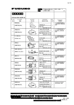
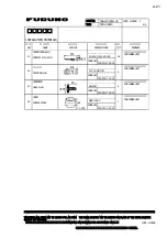
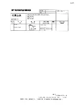
‑3
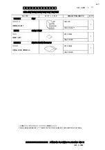
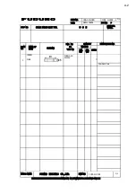
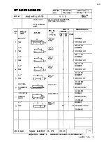
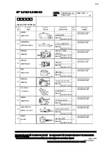
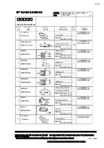
INSTALLATION MATERIALS
工事材料表
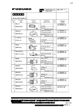
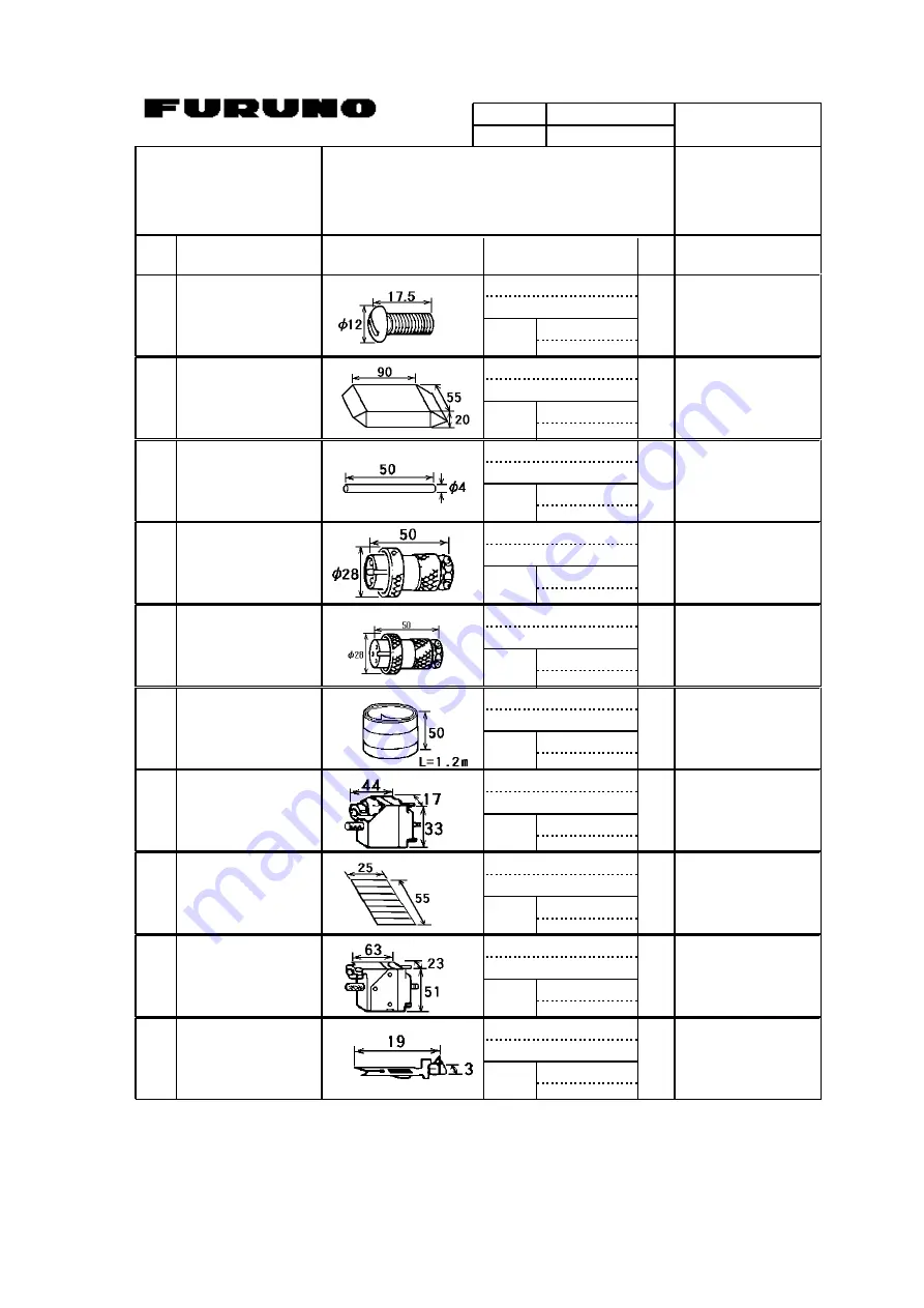
10CC‑X‑9401
M8化粧ビス
PANEL SCREW
10‑054‑1144‑0
4
指示装置用
FOR DISPLAY UNIT
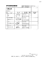
100‑195‑970‑00
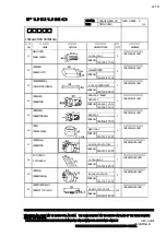
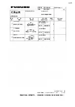
11
CODE NO.
クーラーパテ
COOLER PUTTY
200Gイリ シロイロ
2
指示装置用
FOR DISPLAY UNIT
000‑807‑621‑00
12
CODE NO.
イラックスチューブ(A)
INSULATION TUBE(A)
4.0X0.3 キイロ *5CM*
1
指示装置用
FOR DISPLAY UNIT
000‑100‑923‑00
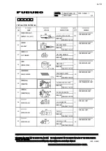
13
CODE NO.
コネクタ(NCS)
CONNECTOR
NCS‑252‑P
1
指示装置用
FOR DISPLAY UNIT
000‑506‑501‑10
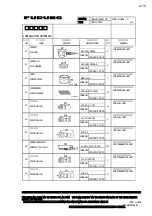
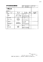
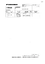
14
CODE NO.
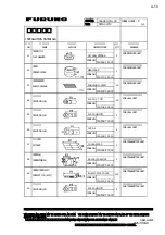
NCS‑252‑P *ROHS*
000‑160‑150‑10
コネクタ(NCS)
CONNECTOR(NCS)
NCS‑253‑P
1
指示装置用
FOR DISPLAY UNIT
000‑506‑503‑10
15
CODE NO.
アース板
COPPER STRAP
WEA‑1004‑0
1
指示装置用
FOR DISPLAY UNIT
500‑310‑040‑00
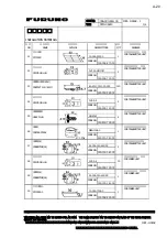
16
CODE NO.
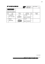
コネクタ(8016)
CONNECTOR
00‑8016‑020‑313‑703V
1
受信装置用
FOR RECEIVER UNIT
000‑111‑143‑00
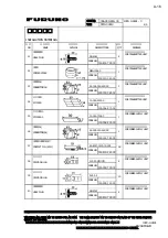
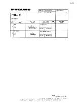
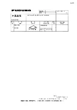
17
CODE NO.
P貼りマーク.11.
P STICKER.11.
10‑026‑0619‑0
1
受信装置用
FOR RECEIVER UNIT
100‑014‑880‑00
18
CODE NO.
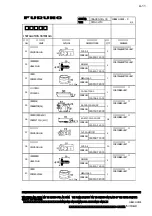
コネクタ(54)
CONNECTOR(54)
54‑038‑000‑601/SC
3
受信装置用
FOR RECEIVER UNIT
000‑132‑081‑00
19
CODE NO.
コンタクト ピン(8017)
CONTACT PIN (8017)
60‑8017‑0313‑00‑339
114
受信装置用
FOR RECEIVER UNIT
000‑519‑542‑00
20
CODE NO.
(略図の寸法は、参考値です。 DIMENSIONS IN DRAWING FOR REFERENCE ONLY.)
FURUNO ELECTRIC CO .,LTD.
10CC‑X‑9401
型式/コード番号が2段の場合、下段より上段に代わる過渡期品であり、どちらかが入っています。 なお、品質は変わりません。
TWO TYPES AND CODES MAY BE LISTED FOR AN ITEM. THE LOWER PRODUCT MAY BE SHIPPED IN PLACE OF THE UPPER PRODUCT.
QUALITY IS THE SAME.
C1292‑M02‑B
A-14
Summary of Contents for CSH-23
Page 1: ...COLOR SCANNING SONAR MODEL CSH 23 23F 24 24F Back ...
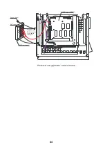
Page 9: ...4 Figure 3 2 Maintenance space example sonar compartment ...
Page 17: ...12 4 WIRING 4 1 Cable Configuration Figure 4 1 Cable configuration ...
Page 53: ...A 4 ...
Page 54: ...A 5 ...
Page 61: ...A 12 ...
Page 71: ...A 22 ...
Page 72: ...A 23 ...
Page 73: ...A 24 ...
Page 74: ...A 25 ...
Page 75: ...A 26 ...
Page 76: ...A 27 ...
Page 77: ...A 28 ...
Page 78: ...A 29 ...
Page 79: ......
Page 80: ...D 2 ...
Page 81: ...Y Hatai D 3 ...
Page 82: ...D 4 ...
Page 83: ...Oct 31 03 D 5 ...
Page 84: ...D 6 ...
Page 85: ...D 7 ...
Page 86: ...D 8 ...
Page 87: ...Dec 10 02 D 9 ...
Page 88: ...D 10 ...
Page 89: ...D 11 ...
Page 90: ...D 12 ...
Page 91: ...D 13 ...
Page 92: ...D 14 ...
Page 93: ...D 15 ...
Page 94: ...D 16 ...
Page 96: ...S 2 ...


