background image

9

N

A

C

S

O

T

U

A

H

T

D

I

W

;

h

t

d

i

w

n

a

c

s

e

h

t

s

t

e

S

±

,

0

1

±

,

0

2

±

r

o

0

4

±

e

d

i

w

a

e

s

U

.

)

s

e

e

r

g

e

d

n

i

(

0

6

e

c

n

o

t

i

g

n

i

w

o

r

r

a

n

,

a

e

r

a

n

a

c

s

a

f

o

h

c

r

a

e

s

l

a

r

e

n

e

g

a

t

c

u

d

n

o

c

o

t

h

t

d

i

w

.

d

e

t

c

e

t

e

d

s

i

l

o

o

h

c

s

h

s

i

f

a

H

T

D

I

W

T

L

I

T

O

T

U

A

;

)

s

e

e

r

g

e

d

n

i

(

h

t

d

i

w

t

l

i

t

c

i

t

a

m

o

t

u

a

e

h

t

t

e

s

o

t

d

e

s

u

s

i

u

n

e

m

s

i

h

T

±

-

2

±

,

0

1

±

-

4

±

,

4

1

±

-

6

±

r

o

,

0

2

±

-

0

1

±

n

i

s

r

e

b

m

u

n

o

w

t

e

h

T

.

6

2

e

s

u

n

i

e

g

n

a

r

e

h

t

s

a

s

e

g

n

a

h

c

h

t

d

i

w

e

h

t

t

a

h

t

s

w

o

h

s

g

n

i

t

t

e

s

h

c

a

e

e

h

t

r

o

f

e

n

o

t

h

g

i

r

d

n

a

e

g

n

a

r

t

s

e

g

n

o

l

e

h

t

r

o

f

r

e

b

m

u

n

t

f

e

l

;

s

e

g

n

a

h

c

.

e

g

n

a

r

t

s

e

t

r

o

h

s

L

G

N

A

M

A

E

B

R

O

H

e

d

i

w

t

c

e

l

e

S

.

e

l

g

n

a

m

a

e

b

l

a

t

n

o

z

i

r

o

h

e

h

t

t

c

e

l

e

s

o

t

d

e

s

u

s

i

u

n

e

m

s

i

h

T

.

n

o

i

t

a

n

i

m

i

r

c

s

i

d

g

n

i

r

a

e

b

r

e

t

t

e

b

r

o

f

w

o

r

r

a

n

;

e

s

u

l

a

r

e

n

e

g

r

o

f

L

G

N

A

M

A

E

B

R

E

V

r

o

f

e

d

i

w

;

e

s

u

l

a

r

e

n

e

g

r

o

f

w

o

r

r

a

n

t

c

e

l

e

S

.

e

l

g

n

a

m

a

e

b

l

a

c

i

t

r

e

v

e

h

t

s

t

e

S

e

d

i

w

e

h

t

t

a

h

t

e

t

o

N

.

d

e

e

p

s

h

g

i

h

a

t

a

n

w

o

d

d

n

a

p

u

s

m

i

w

s

h

c

i

h

w

h

s

i

f

n

o

i

t

c

e

t

e

d

h

s

i

f

t

u

b

y

l

l

a

c

i

t

r

e

v

a

e

r

a

e

d

i

w

a

h

c

r

a

e

s

o

t

s

w

o

l

l

a

e

l

g

n

a

m

a

e

b

o

s

l

a

e

t

o

N

.

s

d

a

e

r

p

s

r

e

w

o

p

d

e

t

t

i

m

s

n

a

r

t

e

h

t

e

c

n

i

s

d

e

n

e

t

r

o

h

s

s

i

e

g

n

a

r

d

e

y

a

l

p

s

i

d

s

i

o

h

c

e

m

o

t

t

o

b

e

h

t

,

r

e

t

a

w

w

o

l

l

a

h

s

a

n

i

d

e

s

u

n

e

h

w

,

t

a

h

t

.

y

l

e

d

i

w

E

V

R

U

C

L

O

C

S

E

R

r

o

l

o

C

e

s

n

o

p

s

e

R

(

)

e

v

r

u

C

e

h

t

n

I

.

s

e

o

h

c

e

g

n

o

r

t

s

d

n

a

k

a

e

w

n

e

e

w

t

e

b

e

c

n

a

l

a

b

e

h

t

s

t

e

s

u

n

e

m

s

i

h

T

s

e

i

r

a

v

)

d

e

y

a

l

p

s

i

d

h

t

g

n

e

r

t

s

o

h

c

e

(

t

u

p

t

u

o

,

n

o

i

t

i

s

o

p

R

A

E

N

I

L

r

e

h

g

i

h

a

t

c

e

l

e

S

.

)

h

t

g

n

e

r

t

s

o

h

c

e

l

a

u

t

c

a

(

t

u

p

n

i

h

t

i

w

y

l

l

a

n

o

i

t

r

o

p

o

r

p

d

e

y

a

l

p

s

i

d

e

r

a

s

e

o

h

c

e

k

a

e

w

:

s

e

o

h

c

e

k

a

e

w

e

z

i

s

a

h

p

m

e

r

e

t

t

e

b

o

t

g

n

i

t

t

e

s

d

r

a

d

n

a

t

s

e

h

T

.

r

e

h

g

i

h

s

e

o

g

r

e

b

m

u

n

e

h

t

s

a

s

r

o

l

o

c

o

h

c

e

r

e

g

n

o

r

t

s

n

i

.

n

o

i

t

i

s

o

p

R

A

E

N

I

L

s

i

g

n

i

t

t

e

s

S

I

S

A

H

P

M

E

R

O

L

O

C

;

y

a

l

p

s

i

d

r

o

l

o

c

e

h

t

n

i

d

e

r

f

o

n

o

i

t

r

o

p

o

r

p

e

h

t

t

e

s

o

t

d

e

s

u

s

i

u

n

e

m

s

i

h

T

d

e

y

a

l

p

s

i

d

e

r

a

s

e

o

h

c

e

n

o

i

t

r

o

p

o

r

p

r

e

t

a

e

r

g

,

r

e

h

g

i

h

s

e

o

g

r

e

b

m

u

n

e

h

t

s

a

.

d

e

r

n

i

G

O

R

P

Y

E

K

C

N

U

F

2

F

d

n

a

1

F

r

o

f

g

n

i

t

t

e

s

d

e

n

i

f

e

d

-

r

e

s

u

r

e

t

s

i

g

e

r

o

t

d

e

s

u

s

i

u

n

e

m

s

i

h

T

.

g

n

i

t

t

e

s

t

l

u

a

f

e

d

t

e

s

o

t

s

i

Y

R

O

T

C

A

F

.

s

y

e

k

Summary of Contents for CSH-5 MARK-2

Page 1: ...COLOR SCANNING SONAR CSH 5 MARK 2 ...

Page 2: ... s h i n o m i ya J a p a n Tel e p h o n e 0 7 9 8 6 5 2 111 Tel ef a x 0 7 9 8 6 5 4 2 0 0 Yo ur Loc al Ag en t De aler All rights reserved PUB No OME 12990 C SH 5 M AR K2 DAMI FIRS T ED ITIO N NOV 1995 E DEC 6 2000 Printed in Japan ...

Page 3: ...the top of the equipment Fire or electrical shock can result if a liquid spills into the equipment Immediately turn off the power at the switchboard if the equipment is emitting smoke or fire Continued use of the equipment can cause fire or electrical shock Contact a FURUNO agent for service Make sure no rain or water splash leaks into the equipment Fire or electrical shock can result if water lea...

Page 4: ...result in loss of the transducer or water leakage inside the ship Do not use the equipment for other than its intended purpose Use of the equipment as a stepping stool for example may result in personal injury or equipment damage A warning label is attached to the equip ment Do not remove the label If the label is missing or damaged contact a FURUNO agent or dealer WARNING To avoid electrical shoc...

Page 5: ...6 Eliminating Unwanted Feeble Echoes 16 Displaying Surface Fish Clearly 17 Suppressing Seabed Tail 17 Suppressing Seabed and Sea Surface Reflections in Shallow Fishing Grounds 18 Rejecting Sonar Interference and Noise 18 Selecting Horizontal Beamwidth 19 Selecting Vertical Beamwidth 19 6 ADVANCED OPERATION______________________________ 20 General 20 Measuring Range and Bearing to a Target 20 Detec...

Page 6: ... 47 Marks and Data 51 Event Mark Position Output 52 12 MAINTENANCE ____________________________________ 53 General 53 13 UNIT DIAGNOSTIC TESTS ___________________________ 54 Description of Unit diagnostic Tests 54 14 CHARACTERISTICS OF THE ULTRASONIC WAVE IN WATER ___________________________________________ 58 Sound Velocity 58 Absorption and Attenuation 59 Refraction 60 Adverse Effect of Air Bubb...

Page 7: ...y greatly improves recognition of seabed and concentration distribution and volume of fish schools Various on screen indications keep operator abreast of fishing con ditions Change of control setting is indicated by displaying the new set ting in larger characters for five seconds High power MOS FET transmitter ensures reliable operation un der any condition Control box for operation from a distan...

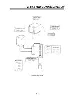
Page 8: ...2 2 SYSTEM CONFIGURATION System Configuration ...

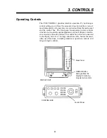
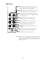
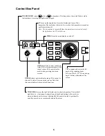
Page 9: ...front panel incorporates mainly controls which do not require frequent adjustment such as brilliance interfer ence rejector and audio volume The control box which is connected to the display unit via a 7 m long connection cable houses the most often used functions including transducer operation controls and range and gain controls Main Panel Control Panel DISPLAY UNIT CONTROL BOX DEMAG Button dema...

Page 10: ...in the radial direction Set at 1 for ordinary use IR Interference Rejector rejects random noise and interference caused by other echo sounders or sonars BRILL adjusts brightness of the screen in eleven steps CONTRAST adjusts the range of brightness between highlights and shadows on the produced image DIMMER adjusts panel main panel and control box panel illumination AUDIO controls the volume of th...

Page 11: ... menu display on and off GAIN adjusts the receiver sensitivity Adjust it for clear presentation of fish school echoes This control is also used to change settings on menu screens RANGE selects a picture display range This control is also used to select items on menu screens Note that this control endlessly turns in both directions TILT continuously varies the tilt angle of the sounding beam betwee...

Page 12: ...k near the own ship position mark and press the R B key OFF CENTER moves the own ship s mark to a desired location on the screen in steps of 1 6 of screen radius To off center the screen place trackball mark on location to offcenter and press the OFF CEN TER key To reset the off centered own ship s mark press the OFF CENTER key again AUTO TILTautomatically tilts the sounding beam up and down withi...

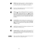
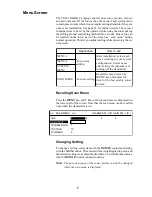
Page 13: ...i f n o c r o r e c u d s n a r t e h t g n i s i a r r e t f a r e t t i m s n a r t e h t f f o g n i n r u t 2 U N E M M E T S Y S U N E M U N E M N A C S g n i t t e s r e s u r o F y b n e e r c s u n e m e h t l l a c e R e h t t s u j d a d n a y e k U N E M r a n o s y t i l a u q t s e b e h t r o f m e t i e r u t c i p Recalling Scan Menu Press the MENU key and 5 lines of the menu items...

Page 14: ... s u d n a e s u l a m r o n r o f 0 1 o t t e S m u m i x a m 0 1 d n a h s i f s e r u c s b o o h c e d e b a e s r o n o i t c e l f e r e c a f r u s a e s n e h w r e w o p e h t t a h t e t o N s n o i t a r e p o r e t a w w o l l a h s d n a e g n a r t r o h s n i s l o o h c s d e g n a h c s i g n i t t e s e h t r e t f a s d n o c e s 0 1 s e g n a h c r e w o p t u p t u o H T G N E...

Page 15: ...l a c i t r e v a e r a e d i w a h c r a e s o t s w o l l a e l g n a m a e b o s l a e t o N s d a e r p s r e w o p d e t t i m s n a r t e h t e c n i s d e n e t r o h s s i e g n a r d e y a l p s i d s i o h c e m o t t o b e h t r e t a w w o l l a h s a n i d e s u n e h w t a h t y l e d i w E V R U C L O C S E R r o l o C e s n o p s e R e v r u C e h t n I s e o h c e g n o r t s d n ...

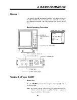
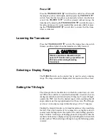
Page 16: ...ation for magnetic function card 4 Turn transmitter on 1 8 Turn power ON OFF 6 Adjust gain 3 Select display range OUTPUT 10 PL 10 TVG Far Near 5 5 AGC 0 NOISE LIM 3 VP 1 IR OFF 5 Set tilt angle CONTROL SETTINGS Turning the Power On Off Power On Press the POWER switch on the main panel The lamp at the left of the switch lights Note The Display and the Transceiver are checked for proper op eration e...

Page 17: ...on the control box is used to select a display range The range selected is displayed at the top center of the screen Setting the Tilt Angle The tilt angle shows the direction to which the sound wave is emit ted When the sound wave is emitted horizontally it is said to be zero 0 degrees and when emitted vertically 90 degrees To set a tilt angle operate the TILT lever for the desired angle while wat...

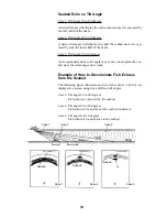
Page 18: ...may not capture the sea bed since the returning echo is weak Example of How to Discriminate Fish Echoes from the Seabed The following figure illustrates how two fish schools a and b are displayed on screen using three different tilt angles Case 1 Tilt angle 30 to 40 degrees Fish school is obscured by the seabed Case 2 Tilt angle 10 to 20 degrees Fish school is located above the seabed midwater Cas...

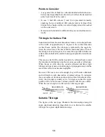
Page 19: ... sea surface and one half of the emitted sound goes upward toward the sea surface This causes a half of the emitted sound to be reflected back toward the transducer and displayed on the screen as sea surface reflections When the sea is calm since the sound is reflected just like a light hitting a mirror at a narrow incident angle it propagates away and the sea surface reflections become negligible...

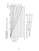
Page 20: ...14 TILT ANGLE Tilt angle vs Beam Coverage 20 40 40 80 60 120 80 160 100 200 200 400 Depth m 100 200 200 400 300 600 400 800 Range m 0 5 10 15 13 23m 100m 46m 200m 68m 300m Vertical Width of Sonar Beam ...

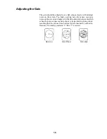
Page 21: ... a setting not only causes excessive noise on the screen and makes it difficult to discriminate wanted fish echoes but also causes seabed echoes to be painted in strong colors resulting that the echoes from bottom fish are masked by seabed re flections Normally positions 3 thru 7 are used Gain Low Gain Proper Gain High ...

Page 22: ...choes on short rang is suppressed and gradually increased as range increases so that similar targets are displayed in the similar intensities irrespective of the ranges to them The CSH 5 MARK 2 incorporates two TVG function NEAR and FAR and they mainly compensate for propagation loss on short and long ranges respectively centered at the ranges shown below Setting a TVG in the scan menu larger smal...

Page 23: ...ed are sometimes difficult to detect because you have to discriminate them in the seabed reflections The AGC control and PULSELENGTH in the scan menu if used properly decrease the tail of seabed reflec tions making it easier to discriminate bottom fish AGC Control The AGC control functions to automatically reduce the receiver gain only against strong echoes such as the seabed or a large fish schoo...

Page 24: ...GC adjusted with OUTPUT maintained high OUTPUT decreased with gain maintained constant Fish echo Fish echo weakened Rejecting Sonar Interference and Noise While observing the sonar picture you may encounter occasional or intermittent noise and interference as shown below These are mostly caused by on board electronic equipment engine or propeller noise or electrical noise from other sonars being o...

Page 25: ...e nearby at the same transmission interval as that of own ship s sonar interference ring caused by other sonars are displayed To erase the interference ring from the screen reduce the TX cycle setting on the scan menu screen See page 8 Note When the sonar is used in a shallow water with the range set between 100 m and 200 m and the TX cycle at 10 seabed reflections caused by the transmission which...

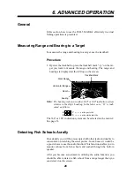
Page 26: ...n either 360 or 180 indication system relative to the ship s heading In the latter case B is indi cated as follows B P on the port side B S on the starboard side The 360 or 180 indication system can be selected on the menu 2 See page 33 Detecting Fish Schools Aurally Occasionally you will be preoccupied with other tasks and unable to concentrate on watching the sonar picture In such cases it would...

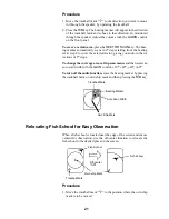
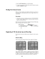
Page 27: ...o in the di rections of 2 steps To change the coverage area call up scan menu and then select an auto scan width with the GAIN control 10 20 40 60 To turn off the audio function erase the bearing marker by placing the trackball mark on own ship mark and then pressing the R B key Trackball Mark Bearing Marker Auto Scan Width Own Ship Mark Relocating Fish School for Easy Observation When a fish scho...

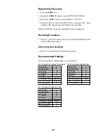
Page 28: ...er Present tilt angle R 800 T 8 10 Registering F1 F2 function key and Recalling Function keys provide user defined sonar settings by one key opera tion Default setting These keys are preset at factory for one key operation as follows TX OUTPUT PULSELENGTH TX CYCLE TVG NEAR TVG FAR HOR BEAM ANGLE VER BEAM ANGLE RES COL CURVE COL EMPHASIS 8 7 10 6 6 NARROW WIDE 3 2 F1 For detection of near range Fac...

Page 29: ...celing the recalling 1 Press F1 or F2 again The LED lamp goes off Recommended Settings We recommend the function key be set as follows TX OUTPUT PULSELENGTH TX CYCLE TVG NEAR TVG FAR HOR BEAM ANGLE VER BEAM ANGLE RES COL CURVE COL EMPHASIS 8 7 10 5 5 NARROW NARROW LINEAR 3 For detection of surface fish school TX OUTPUT PULSELENGTH TX CYCLE TVG NEAR TVG FAR HOR BEAM ANGLE VER BEAM ANGLE RES COL CUR...

Page 30: ...o i t i s o p s p i h s s w o h S g n i d a e h s p i h s f o n o i t c e r i d k r a M l l a b k c a r T n w o n a d n a s k r a m f o n o i t a c o l s t c e l e s k r a m l l a b k c a r t e h T r e v o e r e h w y n a k r a m s i h t s e v o m l l a b k c a r t e h T n o i t i s o p s p i h s n e e r c s e r i t n e e h t k r a M g n i d a e H n e h W e n i l d e t t o d a h t i w n w a r d s ...

Page 31: ... r t e h t g n i c a l p r e t f a d e s s e r p s i y e k k r a m p i h s n w o n o Data Tilt Data The tilt angle set with the TILT level is displayed in 1 steps between 0 and 55 When the auto tilt function is in operation instantaneously changing present tilt angle is indicated below it Range Data Shows the range scale set with the RANGE switch Range Bearing Mark Data The slant range to the rang...

Page 32: ...d condition on the screen the skipper can prevent the net from being damaged by a reef or a shipwreck Narrow tilt angle only half of vertical beam width captures the seabed Seabed Echo a Flat Seabed Tilt Angle 10 15 Seabed is displayed narrower and in a stronger echo colors compared to a Seabed Echo b Flat Seabed Tilt Angle 20 or more A shallow bottom is displayed in a strong echo color and with a...

Page 33: ...l a Sea Surface Fish Tilt Angle 5 10 Because of the narrow tilt angle seabed echo is not displayed Sea surface reflections are present Fish school Seabed b Midwater Bottom Fish Fish echo appears before seabed echo Tilt Angle 30 or more Large midwater fish school is present Fish School Seabed Fish echo appears together with or after seabed echo Tilt Angle 0 20 Since the seabed is displayed in weak ...

Page 34: ... Indication Sea Surface Reflection Wake Awake produced by own ship or another ship can be a strong reflect ing object when the sonar is used with a narrow tilt angle As the wake appears on the screen as a thick continuous line it can be easily distinguished from a fish school On the other hand the wake con tains a lot of air bubbles which attenuate ultrasonic energy making it often difficult to so...

Page 35: ...lobe echo Sidelobe echo The seabed echo detected by sidelobe appears at a certain tilt angle when the sidelobe points vertically Noise and Interference In case the fishing ground is crowded with many fishing boats the sonar is subject to interference from ultrasonic equipment such as an echo sounder sonar etc on board other boats as well as those on board own ship For instance interference from th...

Page 36: ... at the center of the screen and an alarm is released XDCR NOT RETRACTED If this occurs do the following 1 The POWER switch can not be turned off because the transducer can not be retracted Turn off the main breaker for the transceiver unit to stop operation 2 Confirm that the net is not entwined around the transducer 3 Confirm that the breaker inside the raise lower control box mounted on the hul...

Page 37: ...31 Hand Crank hull unit Bottom Down Command LED Red Power LED Green Power SW Breaker ON OFF Main Fuse Fuse for Transceiver Transceiver Unit Power switch Normally position ...

Page 38: ...ng with the GAIN control Note Setting for the items shown in red are locked To unlock the settings change the menu select setting on the system menu Menu 1 The figure below shows menu 1 The contents of the menu 1 are same as the scan menu described on page 8 SCAN MENU RANGE SW U D GAIN SW L R HUE 1 2 3 4 TX OUTPUT 8 PULSELENGTH 7 TX CYCLE 10 TVG NEAR 6 TVG FAR 7 AUTO SCN WDTH 10 20 40 60 AUTO TLT ...

Page 39: ... e s l u p g n i y e k e z i n o r h c n y s o t d e s u s i u n e m s i h T t u p t u o n o i t a z i n o r h c n y s R E K R A M E G N A R e h t s n r u t d e y a l p s i d e b o t s g n i r e g n a r f o r e b m u n e h t s t c e l e s u n e m s i h T f f o s g n i r e g n a r I D N I K R A M 0 8 1 s t c e l e S 0 6 3 r o n o i t a c i d n i g n i r a e b System Menu The figure below shows the ...

Page 40: ...t c n u f t l i t c i t a m o t u a e h t r o f e l g n a t l i t e h t f o e g n a h c f o d e e p s e h t s t e S T I N U r o m o h t a f t e e f r e t e m t n e m e r u s a e m h t p e d f o t i n u e h t s t c e l e S a z a r b i s s a p T C E L E S U N E M d e k c o L s g n i t t e s u n e m f o n o i t a r e t l a s e l b a s i d s e l b a n e u n e m s i h T d e r n i d e y a l p s i d e r ...

Page 41: ...ion Normal Echo Sounder d Sonar Combination Normal Signal on R B Mark a b c d 9 10 1 10 3 5 2 5 3 5 2 5 2 Display Mark Course line mark Current mark Event mark Electronic bearing scale Heading mark and Net sonde data are graphically displayed on the Echo Sounder Combination mode 3 Numeric Information Event Mark Data Horizontal range Depth Latest event marked depth and Bearing Navigational Data Shi...

Page 42: ...e own ship mark is plotted max 10 Erasing Locate the cursor on the event mark and press the EVENT DELETE key GAIN AUTO TILT SECTOR SCAN F1 EVENT R B OFF CENTER F2 EVENT DELETE MENU TILT TRACKBALL 2 Target Lock Mark Use this mark when you want to track fish echoes automatically Target Lock Mark LED lamp Plotting 1 Select TARGET on the range bearing item on the SCAN Menu to activate the mark 2 Move ...

Page 43: ...ETE COLOR on the SCAN menu Echoes are erased in order from weakest to strongest so you may use this function to show only strong echoes 1 Press the MENU key to turn on the menu 2 Select DELETE COLOR with the RANGE control 3 Use the GAIN switch to select desired setting The setting range is 0 10 0 turns off this function 10 erases the strongest color echoes Note that the echoes on the echo sounder ...

Page 44: ...ne appears at the bearing selected at step 5 The rolling and pitching of the ship in the direction of the bearing mark is compensated by automatically adjusting the tilt angle Picture in direction selected with bearing mark is compesnated Note The entire picture is not compensated in the full circle scan ning the tilt angle for each bearing cannot be changed Only one bearing is compensated and bea...

Page 45: ...trol to select FISH ALARM 5 Use the GAIN control to select ON 6 Press the MENU key to close the menu 7 Use the trackball to place the trackball mark on the starting bear ing and press the R B key 8 Use the trackball to place the trackball mark on the ending bear ing and press the R B key Ending point Starting point Alarm area To disable the fish alarm press the R B key Note The starting point may ...

Page 46: ...AN MENU TX Recalling Press the MENU key The SCAN MENU or E S MENU appears on the lower part of the screen Note that the SCAN or E S MENU can be recalled only when the transmitter is ON When the Echo sounder combination mode is selected Changing Setting To change a setting select item with the RANGE control and setting with the GAIN control The selected item is highlighted in green and the selected...

Page 47: ...C S g n i t t e s r e s u r o F d n a y e k U N E M y b n e e r c s u n e m e h t l l a c e R r a n o s y t i l a u q t s e b e h t r o f m e t i e h t t s u j d a e r u t c i p U N E M S E 9 Menu Screen Indications MENU 1 MENU 1 RANGE SW U D GAIN SW L R DISPLAY MODE COMBI 1 NORM TEXT COMBI 2 HUE 1 2 3 4 TX OUTPUT 8 PULSELENGTH 7 TX CYCLE 10 TVG NEAR 6 TVG FAR 7 AUTO SCN WDTH 10 20 40 60 AUTO TLT ...

Page 48: ...SYSTEM SYSTEM MENU SYSTEM MENU RANGE SW U D GAIN SW L R MENU MODE MENU 1 MENU 2 SYSTEM HEADING ADJ 0 AUTO SCN SPD LOW HIGH AUTO TLT SPD LOW HIGH UNIT METERS FEET FATHOMS PA BRA SHIP S SPD BR LOG GY CI NAV LOG PULSE 200 400 CI BAUD RATE 4800 2400 1200 NAV FORMAT CIF NMEA183 NMEA182 NAV BAUD RATE 4800 2400 1200 NAV DATA GPS LC DEC DR LA ALL COMBI SCALE RIGHT LEFT MENU SELECT LOCK UNLOCK SUB TEXT IND...

Page 49: ...ANGE BEARING NORMAL TARGET STAB FISH ALM FISH ALARM ON OFFF ALARM LEVEL 9 HOR BEAM ANGL WIDE NARROW VER BEAM ANGL WIDE NARROW RES COL CURVE LINEAR 1 2 3 COL EMPHASIS 1 LOW 2 3 4 HIGH FUNC KEY PROG FUNC1 FUNC2 FACTORY SCAN MENU RANGE SW U D GAIN SW L R MENU MODE SCAN E S E S MENU E S MENU RANGE SW U D GAIN SW L R HUE 1 2 3 4 E S RANGE 320 E S SHIFT 0 E S IR ON OFF E S GAIN 3 0 E S CLUTTER 1 0 E S A...

Page 50: ...rom the echo sounder appears on the lower 2 5ths of the screen NORM TEXT COMBI 1 COMBI 2 9 10 1 10 3 5 2 5 3 5 2 5 Selects the item to erase with the TX key COURSE track SHIP own ship mark EVENT event mark Each pressing of the key deletes eldest track ship or event mark This menu chooses the function of the R B key NORM The echoes in the direction designated by the bearing mark are stabilized agai...

Page 51: ...n output echo strength displayed varies proportionally with input actual echo strength Select a higher setting to emphasize weak echoes Weak echoes are displayed in stronger echo colors as the number goes higher The standard setting is the LINEAR position Adjusts the draft of the own ship according to loading conditions Irrespective of the depth unit selection the draft adjustment is available fro...

Page 52: ... d n o i t i s o p s p i h s n w o e h t s t c e l e S SYSTEM MENU m e t I s t n e t n o C R B D P S P I H S a t a d e n i l e s r u o c s d e e f h c i h w e c r u o s e h t s t c e l e s u n e m s i h T E S L U P G O L s n o i t c e l e s e h T d e t c e n n o c g o l d e e p s e h t f o s n o i t a c i f i c e p s e h t o t r e f e R e l i m s e s l u p 0 0 4 r o 0 0 2 e r a e l b a l i a v a E...

Page 53: ...47 Indications 1 Normal Mode NORM 4 2 5 1 6 6 3 1 2 3 Electronic Bearing Scale Mark Indication Bearing Course Mark 4 5 6 Heading Indication Current Mark Own Ship s Mark ...

Page 54: ...48 2 Normal Text Mode 9 1 0 7 8 7 8 9 Current Indication Position Data Latest Event Mark Data 0 1 Past Event Mark Navigational Data ...

Page 55: ...49 3 Echo Sounder Combination Mode COMBI 1 Normal Echo Sounder 16 Color Bar Sonar Picture Echo Sounder Picture ...

Page 56: ...50 4 Sonar Combination COMBI 2 Normal Signal on R B Mark 16 Color Bar Sonar Picture Signal on R B Mark ...

Page 57: ... speed and direction of three current layers numbered 1 through 3 The current speed is indicated by the length of the vector However no vectors are developed if the current speed is 0 1 knots or less The vector shows current direction The current mark can be erased on the MENU screen In the Normal Mode with Text current speed and direction for three current layers appear in the text area The displ...

Page 58: ... Mark Position Output Connected to a navigator the CSH 5 MARK 2 can output event mark position data to external equipment when the EVENT key is oper ated The data sentence output is SSTLL NMEA IEC 1162 for mat ...

Page 59: ...se 2 every six months Keep heater away Allow room for ventilation Handle with care Corrosion may occur Keep screen and filter clean Put on cover after operation Do not use thinner or benzine for cleaning Use a water moistened soft cloth Keep magnets and cassette tapes away Color may become distorted Hull Unit Display Unit Do not open the cover of the equipment This equipment uses high voltage elec...

Page 60: ...the self test screen press the MENU key for a few seconds When the SINGLE is selected the unit automatically restores the system menu after the test is completed Description of Unit diagnostic Tests Single Test This test checks the Main Board and Transceiver Unit for proper op eration one time after which normal operation is restored After the test is completed the results are indicated as OK norm...

Page 61: ...control box for proper operation PANEL TEST 0 0 0 0 0 0 0 0 0 0 0 0 X 0 0 7 3 0 0 Y 0 0 0 PRESS MENU 2 or 3 SECONDS TO STOP SELFCHECK Main Panel Press each control one by one The figure should change if the control is functioning properly Control Box Repeat the above procedure SIO Test This test checks the input output parts of the Transceiver Unit The results of the test are indicated as OK or NG...

Page 62: ...ST PRESS MENU 2 or 3 SECONDS TO STOP SELFCHECK 16 Color display WHT RED GRN Echo 1 Test The echo 1 test checks echo processing circuits in the display unit for proper operation DISPLAY ECHO TEST PRESS MENU 2 or 3 SECONDS TO STOP SELFCHECK R29 B358 R400 T10 G3 0 240 236 41 281 B ...

Page 63: ...nochrome test bar are dis played PRESS MENU 2 or 3 SECONDS TO STOP SELFCHECK GRAY TEST Echo 2 Test The echo 2 test checks echo processing circuits in the transceiver and display units PRESS MENU 2 or 3 SECONDS TO STOP SELFCHECK Set the VP control on the main panel to OFF position Radial pattern as above is displayed ...

Page 64: ...on in surface water the velocity changes not only by area but also by direction of the wave propagation The equa tion obtained thru numerous measurements is C 1410 4 21θ 0 037θ2 1 145S 0 0168h m s C C 0 1 2 3 4 5 6 7 8 9 10 11 12 13 14 15 16 17 18 19 20 1445 4 1450 0 1454 4 1458 8 1463 1 1467 2 1471 3 1475 3 1479 2 1483 0 1486 7 1490 3 1493 8 1497 3 1500 6 1503 8 1507 0 1510 0 1513 0 1515 9 1518 7...

Page 65: ... ultrasonic wave decreases gradually through reflection refraction and diffusion in water 2 Acoustic energy is absorbed by the viscosity of the medium wa ter and converted into other forms of energy The higher the frequency the greater the absorption and attenuation of the ultrasonic wave as shown below In other words the absorp tion coefficient is a function of the frequency Generally total energ...

Page 66: ...20 18 18 0 5 1 1 5 2 Water Depth Distance Km Water Temp Here a fishing ground off Hokkaido island in Japan is taken as an example Within 100m Propagation path A Big Fish School B small fish school Seaface Large difference in density Fishing Ground off Hokkaido Summer In summer there is a large difference in salinity density below and above the 100 m deep point An ultrasonic wave emitted almost in ...

Page 67: ...600 1800 0 2000 50 0 100 150 Sea depth m 35 30 25 20 15 10 5 0 DEG Blind zone Adverse Effect of Air Bubbles Even infinitesimal air bubbles in sea water liquid medium affect propagation of ultrasonic sound This is because the cubic elasticity of gas is extremely small when compared with that of liquid the air bubbles violently vibrate contract and expand by the action of sound pressure diffusing th...

Page 68: ...generated by own ship Air bubbles in water have a resonant frequency of l5 kHz thru 100 kHz and hence the ultrasonic wave in this frequency range is most strongly affected Reflection at Seabed and Fish School The nature of the seabed is roughly classified into the following four kinds crag sand mud and seaweeds In addition shells and carcass of animals especially coral imbedded in the seabed cause...

Page 69: ...dB Frequency kHz Reflection Loss Mackerel No 1 Reflection Loss Mackerel No 2 Species Sardine Bonito Horse Mackerel Sea Bream Turbot Average Incident Direction of Ultrasonic Wave Back Side Head 1 2 0 13 1 2 0 5 0 8 1 2 1 4 2 2 0 4 0 6 0 9 3 0 45 2 1 2 0 4 ...

Page 70: ...0 350 400 450 500 600 800 1000 1200 1600 110 130 195 260 325 390 455 520 585 650 780 1040 1300 1560 2080 135 160 240 320 400 480 560 640 720 800 960 1280 1600 1920 2560 OFF Center OFF OFF Center ON Maximum Display Range m NOTE 1 Ranges shown for off center on are maximum 2 Under certain circumstances a target fish school may not be detected due to its nature or because of sea conditions even if it...

Page 71: ...5kHz or 68kHz 7 Tilt Angle Tilt Angle 0 to 55 Auto Tilt 2 to 26 selectable 8 Hull Unit Transducer Travel Raising Time Lowering Time Driving System Allowable Ship s Speed Remote electric control 400mm travel 600mm travel 400m 600m 14 sec 20 sec 14 sec 20 sec 18 knots max 16 knots during raise lower operation 9 Other Features Interference Rejector Video Processing Noise Limiter Automatic Tilt Scanni...

Page 72: ... available menu items 44 46 display marks 35 display mode 35 E S menu 43 event mark 36 indications 47 50 marks and data 51 menu description 41 43 menu screen 40 MENU 1 41 MENU 2 42 numeric information 35 operation 36 46 own ship mark 36 SCAN menu 43 specifications 35 SYSTEM menu 42 target lock mark 36 IR control 19 M Main panel 4 Maintenance zinc block replacement 53 Mark description 24 MENU key 5...

Page 73: ...e 29 Single test 54 SIO test 51 Sound velocity 58 System configuration 2 System menu 33 T Tilt angle and discriminating fish echoes from bottom 12 for surface fish 13 general selection 11 TILT lever 5 11 Trackball 5 TRANSDUCER switch 5 11 30 TVG adjustment 16 TX cycle 19 W Wake recognition 28 ...

Reviews: