7. MENU DESCRIPTION
7-3
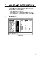
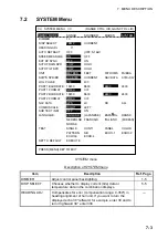
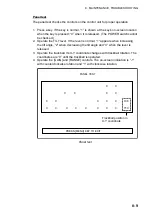
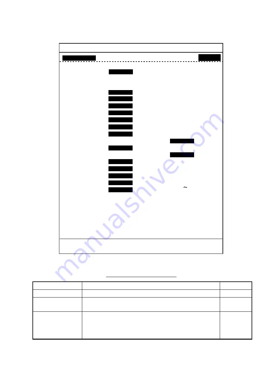
7.2 SYSTEM
Menu
**
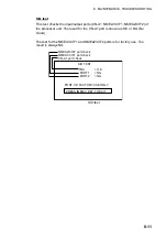
SYSTEM MENU
**
(RANGE CTRL: U/D, GAIN CTRL: L/R)
[MENU MODE]
: SONAR
SOUNDER
MARKS
SYSTEM
DIMMER
: 10
DISP SELECT
:
TEMP
CURRENT
HEADING ADJ
: 0
°
AUTO RETRACT
: OFF (OFF, 5-16kt)
OFF
SPEED MESSAGE :
ON
OFF
EXT KP SYNC
:
OFF
ON
AUTO TRAIN SPD :
LOW
HIGH
AUTO TILT SPD
:
LOW
HIGH
UNIT
:
METERS
FEET
FATHOMS
PA/BRA
SHIP'S SPD/BR
:
LOG/GYRO
CURRENT
NAV DATA
GYRO+NAV
LOG PULSE
:
200
400
PORT1 BAUDRATE : 19200
9600
4800
2400
PORT1 FORMAT
:
NMEA
CIF
PORT2 BAUDRATE : 19200
9600
4800
2400
PORT2 FORMAT
:
NMEA
CIF
NAV DATA
:
GPS
LC
DR
ALL
COMBI SCALE
:
RIGHT
LEFT
SUB TEXT INDI
:
OFF
ON
LANGUAGE
:
ENGLISH
(JAPANESE)
ESPANOL
DANSK
NEDERLND FRANCAIS
ITALIANO
(KOREAN)
NORSK
TEST
: SINGLE
CONTI
PANEL
COLOR
: PATTERN
SIO
ECHO-1
ECHO-2
ECHO-3
ECHO-4
SET TO DEFAULT : EXECUTE
PRESS [MENU] KEY TO EXIT
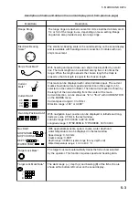
SYSTEM menu
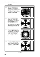
Description of SYSTEM menu
Item Description
Ref.
Page.
DIMMER
Adjust control panel backlighting.
1-5
DISP SELECT
Chooses whether to display current (tide) data or
temperature data in the combination displays.
5-5
HEADING ADJ
Compensates for error (compensation range: 0-359°) in
heading alignment of hull unit. If you want to turn the
displayed echo 30° leftward, for example, enter 30 and to
turn it rightward 30° enter 330.
—


