background image

 1-1

OPERATIONAL OVERVIEW

Equipment Overview

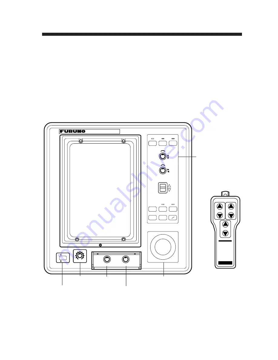
All operations of the CSH-7 are carried out through the display
unit and the remote controller (option). The uncluttered, straight-
forward control panel of the display unit provides intuitive op-
eration. If you change a control setting you will see the associated
reaction on the display almost immediately.

The handy remote controller provides armchair control of range,
gain and tilt functions.

ON

OFF

0

10

BRILL

GAIN

TILT

MENU

EVENT

OFF

CENTER

F1

F2

R

COLOR SCANNING SONAR 

CSH-7

B

–       +

–       +

TX

d

c

BRILL
control

POWER
switch

RANGE

DIMMER

AUDIO

DIMMER
control

AUDIO
control

Trackball

Control
panel

TILT

RANGE

GAIN

Figure 1-1 Display unit, Remote controller

Summary of Contents for CSH-7

Page 1: ...COLOR SCANNING SONAR MODEL CSH 7 ...

Page 2: ...D e a l e r FURUNO ELECTRIC CO LTD c 9 5 2 A s h i h a r a c h o N i s h i n o m i y a J a p a n 6 6 2 T e l e p h o n e 0 7 9 8 6 5 2 1 1 1 T e l e f a x 0 7 9 8 6 5 4 2 0 0 A l l r i g h t s r e s e r v e d Printed in Japan P U B N o O M E 1 3 0 2 0 C S H 7 D A M I ...

Page 3: ...ified personnel should work inside the equipment WARNING CAUTION Use the proper fuse Use of a wrong fuse can result in fire or permanent equipment damage Do not use the equipment for other than its intended purpose Personal injury can result if the equipment is used as a chair or stepping stool for example Do not place objects on the top of the equipment The equipment can overheat or personal inju...

Page 4: ...Standard Markers and Data 2 1 Optional Markers and Data 2 3 MENU OVERVIEW Scan Menu Operation 3 1 Menu 1 Menu 2 System Menu Operation 3 4 FINE TUNING THE PICTURE Eliminating Unwanted Feeble Echoes 4 1 Displaying Surface Fish Clearly 4 2 Suppressing Seabed Tail 4 2 Suppressing Seabed and Sea Surface Reflections in Shallow Waters 4 3 Rejecting Sonar Interference and Noise 4 4 ADVANCED OPERATION Meas...

Page 5: ...6 2 Sea Surface Reflections 6 3 Wake 6 3 False Echo by Sidelobe 6 4 Noise and Interference 6 4 MAINTENANCE Display Unit Maintenance 7 1 Hull Unit Maintenance 7 2 TROUBLESHOOTING When the Transducer Cannot be Retracted 8 1 Diagnostic Tests 8 3 SPECIFICATIONS 9 1 ...

Page 6: ...sidering and purchasing FURUNO equipment Features The FURUNO CSH 7 Color Scanning Sonar is a full circle multibeam electronic scanning sonar which detects and instantaneously displays fish schools and underwater conditions in 16 colors on a 10 non glare high resolution CRT screen Its ease of operation versatility and compact size make it the perfect match for any class of fishing vessel The main f...

Page 7: ...C 1φ 50 60 Hz Ship s Mains 24 VDC HULL UNIT 600 mm stroke 400 mm stroke CSH 7030 CSH 7031 Interface Module CSH 7050 option required to connect external equipment DISPLAY UNIT CSH 7010 NAVIGATOR CURRENT INDICATOR GYROCOMPASS SPEED LOG TILT RANGE GAIN Option Option REMOTE CONTROLLER CSH 7020 ...

Page 8: ...n If you change a control setting you will see the associated reaction on the display almost immediately The handy remote controller provides armchair control of range gain and tilt functions ON OFF 0 10 BRILL GAIN TILT MENU EVENT OFF CENTER F1 F2 R COLOR SCANNING SONAR CSH 7 B TX d c BRILL control POWER switch RANGE DIMMER AUDIO DIMMER control AUDIO control Trackball Control panel TILT RANGE GAIN...

Page 9: ...a radius being the distance between the own ship marker and trackball marker Range and bearing data of the intersection of the two markers are dislayed at the bottom of the screen To turn off the range and bearing markers move the trackball mark near the own ship position and press the R B key Shifts screen center to cursor location Raises lowers the transducer respectively Lamp above a key blinks...

Page 10: ...s the d switch during raising of the transducer The equipment may become damaged Selecting a Display Range Operate the RANGE control to select a display range The range selected appears at the top center of the screen Setting the Tilt Angle The tilt angle shows the direction to which the sound wave is emitted When the sound wave is emitted horizontally the tilt angle is said to be zero degrees and...

Page 11: ...since the re turning echo is weak How to discriminate fish echoes from the seabed The figure below illustrates how two fish schools a and b are displayed on the screen using three different tilt angles Case 1 Tilt angle 30 to 40 degrees Fish school is obscured by the seabed Case 2 Tilt angle 10 to 20 degrees Fish school is located above the seabed midwater Case 3 Tilt angle 0 to 10 degrees Fish sc...

Page 12: ...gle is set to 0 degrees the center line is parallel with the sea surface and one half of the emitted sound goes upward toward the sea surface This causes one half of the emitted sound to be reflected toward the transducer and displayed on the screen as sea surface reflec tions When the sea is calm since the sound is reflected just like a light hitting a mirror at a narrow incident angle it propaga...

Page 13: ...er to it to find out the suitable tilt angle for a given depth detection range 100 200 200 400 300 600 400 800 Range m 0 5 10 15 20 40 40 80 60 120 80 160 100 200 200 400 Vertical width of sonar beam 16 28 m 100 m 100 m 300 m 84 m 200 m Depth m 56 m Tilt angle and beam coverage Figure 1 5 Tilt angle and beam coverage ...

Page 14: ...oo high a setting not only displays excess noise and makes it difficult to discriminate wanted echoes but also causes seabed echoes to be painted in strong colors resulting in echoes being masked by seabed reflections Normally set the control somewhere between positions 3 and 7 Gain low Gain proper Gain high Figure 1 6 Gain settings and resulting picture ...

Page 15: ...e marker Range ring Range marker Bearing marker Range Tilt Trackball marker data Slant range Horizontal range Depth True bearing Trackball marker Heading marker Own ship marker Heading data Requires INTERFACE Board and gyrocompass M Unit of depth measurement Gain Figure 2 1 Standard markers and data ...

Page 16: ... trackball marker location These markers may be erased by placing the trackball marker near the own ship marker and pressing the R B key Range marker The slant range to the range marker and the bearing of the bearing marker are displayed The range rings are inscribed at intervals of 1 4 of the range in use Range ring data is also provided every two range rings The range ring interval can be change...

Page 17: ...s and data in the normal mode 184 16 199 B E N 187 186 16 B 23 S E N R 300 T 5 G 3 0 E S W 300 N 3 2 1 Trackball marker data Tidal current marker Own ship event marker Course line Electronic bearing scale Heading indication Latest event marker Latest event marker data Past event marker Trackball marker Figure 2 2 Optional markers and data in the normal mode ...

Page 18: ...493 51 B 52 S NW N R 800T T 5 G 4 0 N S W 3 2 1 Heading indication Latest event marker data 0 0 NW W 174 17 0 34 C1 C2 C3 13 02N 135 16 39E 1 1 315 0 6 25 1 2 64 Position Past event marker Tidal current data Nav data Latest event marker Figure 2 3 Optional markers and data in the normal plus text mode ...

Page 19: ...ompass or speed log connection own ship s course line is plotted by a solid line Course line length is selectable from 5 to 10 times the range in use Course line can be erased through the menu In the normal mode plus text tide speed and direction for three tide layers appear in the text area The method for displaying current direction can be selected through the menu Nav Data S C D T Own Ship Data...

Page 20: ...if it is not already lit 2 Press the MENU key The first five items of the Scan menu appear The figure below shows the entire menu SCAN MENU RANGE SW U D GAIN SW L R DEGAUSS AUTO DEGAUSS DISPLAY MODE TX OUTPUT PULSELENGTH TX CYCLE TVG NEAR TVG FAR AGC NOISE LIM VP IR MARK ERASE HOR BEAM ANGL RES COL CURVE COLOR EMPHASIS FUNC1 PROG FUNC2 PROG USER PROG EXECUTE OFF NORM 10 10 10 10 10 10 10 0 0 COURS...

Page 21: ... t e S t r o h s n i s l o o h c s h s i f s e r u c s b o o h c e d e b a e s r o s n o i t c e l f e r e c a f r u s r e w o p t u p t u o e h t t a h t e t o N s n o i t a r e p o r e t a w w o l l a h s d n a e g n a r d e g n a h c s i g n i t t e s e h t r e t f a s d n o c e s 0 1 s e g n a h c H T G N E L E S L U P s i 0 s g n i t t e s n e v e l e n i h t g n e l e s l u p n o i s s i m s...

Page 22: ... t i w y l l a n o i t r o p o r p t u p t u o s e i r a v k a e w s e o h c e k a e w e z i s a h p m e r e t t e b o t g n i t t e s r e h g i h a t c e l e S s e o g g n i t t e s e h t s a s r o l o c o h c e r e g n o r t s n i d e y a l p s i d e r a s e o h c e R A E N I L s i g n i t t e s d r a d n a t s e h T r e h g i h S I S A H P M E R O L O C e h t r e h g i h e h t y a l p s i d r o...

Page 23: ...VE COL EMPHASIS FUNC1 PROG FUNC2 PROG USER PROG DEGAUSS AUTO DEGAUSS MENU MODE MENU 1 MENU 2 SYSTEM NORM 8 8 10 6 7 0 0GPS 0 0 WIDE LINEAR 1 LOW USER1 USER2 USER1 EXEC OFF TEXT NARROW 1 2 SETUP1 SETUP1 USER2 TIMER 2 3 SETUP2 SETUP2 GYRO 3 4 HIGH SETUP3 SETUP3 Requires INTERFACE Board Locked setting Figure 3 2 Menu 1 3 Operate the RANGE control to select item The selected item is highlighted in gre...

Page 24: ...B f f o n o e l a c s g n i r a e b c i n o r t c e l e s n r u T K R A M T N E R R U C f f o n o k r a m e d i t t n e r r u c e h t s n r u T K R A M E S R U O C s e m i t 5 r o s e m i t 0 1 m o r f t o l p e n i l e s r u o c e h t f o h t g n e l s t c e l e S e s u n i e g n a r e h t I D N I G N I D A E H g n i r a e b e u r t r o h t u m i z a 2 3 n o i t a c i d n i g n i d a e h s t c e ...

Page 25: ...s s t c e l e S g o l d e e p s e h t f o l a u n a m s r o t a r e p o e h t t l u s n o C e l i m s e s l u p E T A R D U A B I C d u a b 0 0 2 1 r o 0 0 4 2 0 0 8 4 e t a r d u a b r o t a c i d n i t n e r r u c s t c e l e S r o t a c i d n i t n e r r u c e h t f o l a u n a m s r o t a r e p o e h t t l u s n o C T A M R O F V A N r o 3 8 1 0 A E M N F I C r o t a g i v a n d e t c e n n o ...

Page 26: ...ncreased as range increases so that simi lar targets are displayed in the similar intensities irrespective of the ranges to them The CSH 7 has two TVG functions NEAR and FAR and they mainly compensate for propagation loss on short and long ranges respectively centered at the ranges shown below The higher the TVG setting the greater the amplification of echoes About 100 m Near Far Figure 4 1 Princi...

Page 27: ...Scan menu Suppressing Seabed Tail As noted earlier fish schools echoes located near the seabed are sometimes difficult to detect because you have to discrimi nate them in the seabed reflections The AGC and PULSELENGTH in the Scan menu if used properly decrease the tail of seabed reflections making it easier to discriminate bottom fish AGC The AGC functions to automatically reduce the receiver gain...

Page 28: ... not be eliminated sufficiently with the aforementioned TVG and AGC especially when the TILT is set to a larger angle in order to track fish schools approaching within 400 m In such cases try to reduce the output power with OUTPUT in the Scan menu without turning down the GAIN The picture becomes clearer when output power is reduced rather than when the GAIN is decreased as illustrated below Fish ...

Page 29: ...of the above two steps has effect on the picture adjust the IR Interference Rejector and NOISE LIM Noise Limiter on the Scan menu as follows Rejecting noise with IR on the scan menu This control is similar to the interference rejector on echo sound ers and radars It is effective for rejecting random noise and sea surface reflections in rough sea conditions Set it so that noise is just eliminated D...

Page 30: ...d Figure 4 3 How TX cycle works Note When the sonar is used in a shallow water with the range set between 100 m and 200 m and the TX CYCLE at 10 sea bed reflections may appear on the screen Reduce the TX CYCLE setting to 7 or 8 to reject them Selecting horizontal beamwidth If you wish to have better bearing discrimination ability to dis tinguish two closely located targets at the same range and di...

Page 31: ...0 or 180 indication system can be selected on Menu 2 Detecting Fish Schools Aurally Occasionally you will be preoccupied with other tasks and un able to concentrate on watching the sonar picture In such cases you can use the audio function to aurally monitor fish echoes through the built in speaker 1 Operate the trackball to move the trackball marker to the direction you want to monitor through th...

Page 32: ... the off center function to re locate the fish school to the desired place on the screen Fish echo Fish echo OFF CENTER key turned on Own ship Trackball marker Figure 5 3 Off center function 1 Move the trackball marker to the position where the own ship mark is to be moved 2 Press the OFF CENTER key 3 To cancel the off center function and shift own ship marker back to the center of the screen pres...

Page 33: ...d three task specific pro grams Setup 1 2 3 The default settings of these programs are shown in the table below Note that the Setup programs can not be changed Table 5 1 Default programs m e t I g n i t t e S m a r g o r P 2 1 r e s U 1 p u t e S l o o h c s h s i F 2 p u t e S f e e r k c e r W 3 p u t e S e g n a r g n o L n o i t c e t e d T U P T U O X T 0 1 8 0 1 0 1 H T G N E L E S L U P 2 8...

Page 34: ...nge the contents of USER 1 or USER 2 do the next procedure Selecting program to use Selecting program to use 1 Press the F1 or F2 key to light the lamp above it 2 Press the TX switch to blink the lamp above it if it is not already blinking 3 Press the MENU key and select Menu 1 4 Operate the RANGE control to select FUNC1 PROG or FUNC2 PROG slected at step 1 5 Operate the GAIN control to select pro...

Page 35: ...ship event marker 1 Place the trackball marker on the location desired for an event marker For own ship event marker place the trackball marker at own ship marker at screen center 2 Press the EVENT key The latest event marker appears at the cursor location and event marker data horizontal distance present depth depth when marker was plotted and bearing is displayed at the lower left side of the sc...

Page 36: ...e sea bed condition on the display the skipper can prevent net dam age A Flat seabed Tilt angle 10 to 15 B Flat seabed Tilt angle 20 or more C Sloping seabed Tilt angle 20 or more Seabed Shallow bottom is displayed in a strong color and with a short tail Seabed is displayed narrower and in stronger colors when compared to A Narrow tilt angle Only half of vertical beam width captures the seabed Fig...

Page 37: ...urface fish Tilt angle 5 to 10 B Midwater bottom fish Tilt angle 30 or more Fish echo which appears before seabed can be detected Tilt angle 0 to 20 Fish echo which appears together with or after seabed can be detected Seabed Fish school Sea surface reflections Fish school Seabed echo not displayed because of narrow tilt angle Sea surface reflections are present Fish school Large midwater fish sch...

Page 38: ... Tx 16 Rx 19 Figure 6 3 Sea surface reflections Wake A wake produced by own ship or another ship can be a strong reflecting object when a narrow tilt angle is used As the wake appears as a thick continuous line it can be easily distinguished from a fish school A wake contains many air bubbles which attenuate ultrasonic energy making it difficult to sound beyond the wake Own ship Other ship Wake pr...

Page 39: ...ed echo detected by sidelobe appears at a certain tilt angle when the sidelobe points vertically Figure 6 5 Sidelobe echoes Noise and Interference Interference from a sonar on board another ship appears on the screen as shown in A below This interference can be suppressed by changing the TX CYCLE setting in the Scan menu Interfer ence from electrical equipment on board own ship appears as shown in...

Page 40: ...he display unit Handle the equipment with care Damage can cause corrosion DISPLAY UNIT Clean the screen and filter regularly Cover the equipment when it is not in use Heat can damage the equipment Allow sufficient ventilation Keep heater away from the equipment Magnets or magnetic material can can distort the picture An anti static spray may be used to clean the screen Do not use chemical based cl...

Page 41: ...transducer face yearly Apply single coat of MARINE STAR 20 Mod Red N anti foulant to transducer face to keep marine life off the transducer Figure 7 2 Hull unit maintenance CAUTION The zinc block near the transducer must be replaced yearly The junction between the transducer and main shaft may corrode which can result in loss of the transducer or water leakage inside the ship ...

Page 42: ... If this occurs do the following 1 The power switch cannot be turned off because the trans ducer cannot be retracted Turn off the main breaker for the transceiver unit to stop operation 2 Confirm that the net is not entwined around the transducer 3 Confirm that the breaker inside the hull unit is on 4 Check the mains fuse in the transceiver unit 5 Apply the power again Check if the transducer is r...

Page 43: ...crew from cover Shaft moves 600 mm per 120 turns of crank Motor gear Tighten screws Use screw from cover Shaft moves 600 mm per 210 turns of crank a When crank is attached to shaft gear Requires greater force but less turns b When crank is attached to motor gear Requires less force but more turns Figure 8 1 How to use the hand crank CAUTION POSSIBILITY OF INJURY 1 If breaker hull unit trips do the...

Page 44: ...d the transceiver unit for proper operation one time after which nor mal operation is restored After the test is completed the results of each device checked are indicated as OK or NG No Good to the right of the device checked SINGLE TEST MAIN TRX I F 105 0557 0xx ROM RAM P W 105 0569 000 ROM RAM 105 0267 0xx ROM RAM OK OK OK OK OK OK OK Program no of display unit appears and ROM RAM and password ...

Page 45: ...on PANEL TEST PRESS MENU 2 or 3 SECONDS TO STOP SELFCHECK Press each control one by one Corresponding figure changes if control is normal 0 0 0 0 0 0 0 0 0 0 0 0 0 0 0 0 X 0 0 0 0 Y 0 For Remote Controller Option Figure 8 3 Results of panel test Color test The color test checks for proper display of all colors COLOR TEST PRESS MENU 2 or 3 SECONDS TO STOP SELFCHECK WHT RED GRN ...

Page 46: ...CHECK GRAY TEST Figure 8 5 Gray test display Conti test This test continuously checks the display and transceiver units In addition to the devices checked in the single test the DROM and DRAM are also checked CONTI TEST MAIN 105 0557 0xx TRX 105 0569 0xx I F 105 0267 0xx ROM RAM P W DRAM DPRAM ROM RAM DROM ROM RAM DPRAM GYRO LOG OK OK OK OK OK OK OK OK OK OK OK OK OK PRESS MENU 2 or 3 SECONDS TO S...

Page 47: ...NDS TO STOP SELFCHECK For service technicians special test connector required to check NG appears when no test connector is connected Figure 8 7 Results of SIO test Echo 1 test This test checks the echo processing circuits in the display unit for proper operation DISPLAY ECHO TEST PRESS MENU 2 or 3 SECONDS TO STOP SELFCHECK R 400 T 10 G 3 0 R 29 B 358 240 236 41 281 ª B ...

Page 48: ...cks echo processing circuits in the display unit and transceiver unit PRESS MENU 2 or 3 SECONDS TO STOP SELFCHECK TRX ECHO TEST Figure 8 9 Echo 2 test display Note Appearance of above test pattern may vary slightly depending on the frequency or internal settings ...

Page 49: ... range tilt angle gain Trackball marker data slant range horizontal range depth bearing Event marker data horizontal range and depth and bearing at time of entry Bearing and range marker data bearing range Setting data New gain range or tilt setting appears in larger characters for five seconds Nav data speed course depth water tempera ture Own ship data position in L L or TDs Tidal current data s...

Page 50: ...oes in the direction of the bearing marker are audibly monitored with built in loudspeaker Audio output 2 W Audio frequency 1 kHz Transmitter Unit Transmitter section High power MOS FET amplifier Receiver section Low noise superheterodyne continuously scanning beam forming GAIN TVG near far AGC Tx frequency 55 kHz or 70 kHz m e g n a R m e g n a r y a l p s i d m u m i x a M F F O r e t n e c f f ...

Page 51: ...5 Transceiver unit hull unit Munsell 2 5G 7 2 Newtone No 5 Environmental Conditions Temperature 0 C to 50 C Humidity Less than 85 0 3 0 7 H S C 1 3 0 7 H S C l e v a r t r e c u d s n a r T m m 0 0 6 m m 0 0 4 e m i t g n i s i a R c e s 5 2 c e s 0 2 e m i t g n i r e w o L c e s 0 2 c e s 4 1 m e t s y s g n i v i r D l o r t n o c c i r t c e l e e t o m e R d e e p s s p i h s e l b a w o l l ...

Reviews:

Related manuals for CSH-7