background image

COLOR SCANNING SONAR

MODEL

CSH-7

Summary of Contents for CSH-7

Page 1: ...COLOR SCANNING SONAR MODEL CSH 7 ...

Page 2: ...g e n t D e a l e r FURUNO ELECTRIC CO LTD c 9 5 2 A s h i h a r a c h o N i s h i n o m i y a J a p a n 6 6 2 T e l e p h o n e 0 7 9 8 6 5 2 1 1 1 T e l e f a x 0 7 9 8 6 5 4 2 0 0 A l l r i g h t s r e s e r v e d Printed in Japan P U B N o I M E 1 3 0 2 0 D C S H 7 T A T A ...

Page 3: ...ial and installed in accordance with the pro cedures set forth in this manual Use of other material or procedure is the responsibility of the shipyard In any case the tank should be installed so the hull will not be seriously damaged in the event the tank is struck by an object CAUTION Use the proper fuse Use of a wrong fuse can result in fire or permanent equipment damage Replace zinc block near ...

Page 4: ...ii ...

Page 5: ...iring the Hull Unit 2 2 2 3 Wiring the Transceiver Unit 2 3 2 4 Wiring the Display Unit 2 4 2 5 Synchronizing Transmission with Other Equipment 2 5 2 6 How to Unplug the XH Connector 2 7 CHECKS AND ADJUSTMENTS 3 1 General Checks 3 1 3 2 Heading Alignment 3 3 3 3 Sea Trial 3 4 INSTALLATION OF INTERFACE MODULE CSH 7050 option 4 1 Introduction 4 1 4 2 Installation 4 2 ASSEMBLING TRANSCEIVER FRAME Opt...

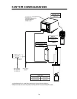
Page 6: ...iv SYSTEM CONFIGURATION ...

Page 7: ...0 0 1 P C 5 s e i r o s s e c c A 0 1 3 4 0 3 0 P F t e s 1 6 s t r a P e r a p S 0 0 3 2 0 0 1 P S t e s 1 7 e t o m e R r e l l o r t n o C 0 4 0 7 H S C t e s 1 0 0 2 4 0 0 1 P C s l a i r e t a m t s n i h t i W Optional Equipment e m a N e p y T y t Q o N e d o C s k r a m e R 1 e l u d o M e c a f r e t n I 0 5 0 7 H S C t e s 1 t i n u y a l p s i d n i t l i u B 2 e m a r F r e v i e c s n...

Page 8: ...mperature range of the display unit is 0 50 C Provide sufficient ventilation Select location where vibration is minimal Locate the equipment away from magnets and magnetic materials Keep the transducer away from oil Oil can corrode the cable Do not expose the transducer to hot water Hot water can damage the transducer Do not turn on the equipment with the transducer exposed to air Exposing the tra...

Page 9: ...rolling effect 1 2 1 3 Within 1 m Figure 1 1 Installation location for hull unit Select a place where interference from the transducers of other sounding equipment is mini mal The hull unit should be at least 2 5 meters away from the transducers of other sounding equipment An obstacle in the fore direction not only causes a shadow zone but also aerated water resulting in poor sonar performance Be ...

Page 10: ... How to shorten the retraction tank Reletion of tank length and shft length Shaft supplied 945 1300 1550 2350 Shaft Cut length Shaft length Cut length Shaft length Cut length Shaft length Cut length Shaft length Cut length Hull Unit Tank length 400 Stroke 550 945 0 600 Stroke 750 1300 0 800 1365 185 850 1415 135 900 1465 85 950 1515 35 1000 1550 0 1100 1665 685 1200 1765 585 1300 1865 485 1400 196...

Page 11: ...ssembly to the main body flange with the trunnion shaft Split pin Trunnion shaft Main body flange Raise lower drive assy Flat washer Flat washer Figure 1 4 How to fasten raise lower drive assy to main body flange 2 Coat the top of the main shaft with a small amount of grease Pass the main shaft through the main body flange and fix it temporarily with the shaft retainer The shaft retainer should be...

Page 12: ...nch Socket set screw M5 x 10 2 pcs If it is difficult to pass the transducer cables through the flat washers of the cable gland unbind the transducer cables and pass them one by one Flat washer Note Screw shaft 50 mm into transducer flange 50 mm 140 mm Figure 1 7 Fastening main shaft to transducer 5 Inscribe bow mark on the top end of the main shaft and install fastening band and cable gland BOW m...

Page 13: ...0 m travel type and 140 mm for 400 mm travel type Bow mark Tank guide Align with bow mark on trans ducer flange 340 mm for 600 mm travel type 140 mm for 400 mm travel type M10 x 55 M10 SW Spring washer Figure 1 10 Installing the tank guide 8 Attach zinc block to main shaft CAUTION The zinc block near the transducer must be replaced yearly The junction between the transducer and main shaft may corr...

Page 14: ... the hull unit to the retraction tank 10 Fix anti vibration stays to the retraction tank Anti vibration stay Figure 1 13 Fixing anti vibration stays to retraction tank 11 Orient the main shaft so that the bow mark faces ship s bow and fix it securely with the shaft retainer Loosen shaft retainer and rotate main shaft so the bow mark on it faces ship s bow Bow mark Ship s bow Figure 1 14 Orienting ...

Page 15: ...1 8 ...

Page 16: ...1 9 ...

Page 17: ...ER switch M4 x 8 4 pcs Screw shaft gear Motor gear OFF ON Figure 1 15 Hull unit 3 Attach the hand crank onto the screw shaft gear or motor gear depending on circumstance a When crank is attached to shaft gear Requires greater force but less turns Hand crank Shaft gear Tighten screw Use screw from cover Shaft moves 600 mm per 120 turns of crank Motor gear Tighten screws Use screw from cover Shaft m...

Page 18: ...ver unit can be mounted on the hull unit with Transceiver Frame Kit op tion See page 5 1 for details 1 4 Mounting the Display Unit Select the mounting location considering the following condi tions Select a location where the display unit can be easily oper ated while observing the fishing ground or area surrounding the vessel Locate the unit at least 1 meter away from a magnetic compass and equip...

Page 19: ...nit Ground the equipment with a copper plate Ground the equipment to prevent mutual interference CAUTION SCREEN FOCUS Earth terminal DISPLAY UNIT Earth terminal TRANSCEIVER UNIT Figure 1 19 Location of earth terminals on display unit and transceiver unit ...

Page 20: ... m 10S1925 30 m 250V DPYCY 3 5 or equivalent 250V DPYCY 1 25 or equivalent Ship s mains 24 VDC TRANSCEIVER UNIT DISPLAY UNIT 1 1 Fabricate cable in field For shaft length of 1300 or 945 mm remove outer sheath until point a below a DPYCY 1 25 Armar Vinyl sheath Conductor S 1 25 mm2 φ 1 35 mm DPYCY 3 5 Armar Vinyl sheath Conductor S 3 5 mm2 φ 2 4 mm Figure 2 1 Wiring diagram ...

Page 21: ...ı on the raise lower assy and position them as shown below Temporarily tighten clamp ı a b c d e f a b c d e f Cable clamp ı Cable clamp Å Example Wire a of clamp Å to a of clamp ı Figure 2 3 Cable clamps and positioning of cables 3 Adjust the cable lengths between cable clamps a and b as follows Cable length between a of Å and a of ı 600 stroke 660 mm 400 stroke 580 mm 4 Adjust slack of five othe...

Page 22: ...P signal I O video sounder etc Cable from hull unit Cable from display unit CN B2 J6 CN B1 J5 CN B4 J7 J9 J3 J4 J1 J3 J2 P1 P3 P2 1 3 5 2 4 6 Number inscribed on sheath Connect wire according to number Cable clamp Cable clamp Ground at thin metallic band of cable Fasten wire here Transducer cable 40 5 Vinyl sheath Armor White Black TB B1 CN B3 How to fabricate power cable 100 TB B1 Figure 2 4 Wiri...

Page 23: ...g the Display Unit SCREEN FOCUS Power cable From transceiver Remote controller option Figure 2 5 Display unit rear view How to fabricate the power cable 1 pin 2 pin 3 pin Figure 2 6 How to fabricate the power cable ...

Page 24: ... CSH 7 1 Wiring 2 Sonar 2 Sonar TRANSCEIVER UNIT TRANSCEIVER UNIT DIG Board DIG Board J7 J7 5 6 1 2 INT KPC H INT KPC C EXT KPC H EXT KPC C Figure 2 7 Connection of two sonars 2 DIP switch setting Set DIP switches on the DIG board as follows h c t i w s P I D r a n o S 1 r a n o S 2 3 1 S N O 4 1 S N O 3 Menu setting On Menu 2 set external KP ON for the 2 sonar Refer to the operator s manual for m...

Page 25: ...her type of sonar make the connections as shown below 1 Wiring TRANSCEIVER UNIT DIG Board J7 7 8 EXT KPV GND ES SONAR This equipment accepts KP input of 5 to 15 V TRANSCEIVER UNIT 5 6 EXT KPC H EXT KPC C ES SONAR For current loop signal For voltage signal DIG Board J7 Figure 2 8 Connect of CSH 7 with echo sounder or sonar ...

Page 26: ... for menu setting procedure Reference Outputting KP of CSH 7 to external equipment TRANSCEIVER UNIT DIG Board J7 3 4 INT KPV GND ES SONAR For voltage signal TRANSCEIVER UNIT DIG Board J7 1 2 INT KPC H INT KPC C ES SONAR For current loop signal Figure 2 9 How to output CSH 7 s KP to external equipment 2 6 How to Unplug the XH Connector Use XH connector remove the unplug the XH connector Connector r...

Page 27: ...ucer is completely retracted by hand crank Transducer travel lowered by hand crank Note Clearance under bootom of the transducer should be approx 1 meter in order to check Transducer heading 1 2 1 2 D 8 D 7 1 6 On keel installation Off keel installation Bow mark inscribed on main shaft should face ship s bow Flush with keel Within 1 m Approx 1 cm Min 30 cm BOW mark Result Ref page Rating ...

Page 28: ... s e r p p u S e s i o n f o e c n e r e f r e t n i d n a e s i o n s e t a r e n e g h c i h w t n e m p i u q E r e t t i m s n a r t e n o h p e l e t o i d a r r o t o m y b r a e n t o n e r a c t e t e s V T d e c a l p t o n e r a s e c i v e d c i t e n g a M t i n u y a l p s i d e h t r a e n d n u o r G a h t i w d e d n u o r g s i t i n u h c a E p a r t s r e p p o c 1 1 1 s n i a m...

Page 29: ... and rotate the main shaft Shaft retainer Loosen two bolts Figure 3 2 Hull unit 3 Fasten two bolts unscrewed in step 2 Note 1 Heading can be aligned through the menu if the error is small When the error is large rotate the shaft to correct it the tank guide should be oriented to ship s fore aft direction to reduced shock at the main shift when the ship pitches Note 2 See the operator s manual for ...

Page 30: ...ILT DEPTH 800 m 5 0 N F 0 ENG RPM SPEED SEA CONDITION 0 KTS Ship anchored NL RANGE GAIN TVG TILT DEPTH 800 m 5 0 N F 0 ENG RPM SPEED SEA CONDITION Ship at cruising speed Recording optimum control settings Record optimum control and switch settings and take a photograph of the sonar picture as reference for later service RANGE TILT TVG GAIN OUTPUT TX PULSELENGTH NOISE LIMITER AGC VP INTERFERENCE RE...

Page 31: ... n n o C r o t c e n n o C r o t c e n n o C r e c a p S r e h s a w g n i r p S 1 0 9 1 S 0 1 P 3 3 1 A 6 N C R S P 5 3 1 A 6 N C R S P 0 1 6 1 A 6 N C R S 5 2 Q S 3 M 8 7 8 9 3 1 0 0 0 0 6 6 8 0 5 0 0 0 1 6 6 8 0 5 0 0 0 3 6 6 8 0 5 0 0 0 0 7 8 1 0 8 0 0 0 4 0 2 4 6 8 0 0 0 1 1 1 2 6 6 y s s A e l b a C 0 0 1 2 1 0 0 F S 6 A J M 7 1 8 3 3 1 0 0 0 m 0 1 n o i t p O 0 5 0 2 1 0 0 F P S 6 A J M 4 2...

Page 32: ...ied between J9 on the MAIN Board and J1 on the ITF Board 10P6840 5 Remove dummy plate at rear of display unit and install the connector board assy there 6 Connect the cables from the connector board assy to the ITF Board as follows Connector board assy ITF Board NAV CI GYRO LOG CN 4A J3 CN 5A J4 CN 6A J6 CN 7A 7 Reattach the cover MAIN Board 10P6835 J9 J1 PMAIN J9 J4 J2 J1 J6 J3 J4 P ITF J3 Cable ...

Page 33: ... e h s a W t a l F 4 0 3 S U S 8 M 0 3 1 4 6 8 0 0 0 7 6 r e h s a W g n i r p S 4 0 3 S U S 8 M 2 6 2 4 6 8 0 0 0 7 Procedure 1 After mounting the hull unit fasten frame 1 to the flange with three hex bolts M20x80 used at tank flange 2 Similairy fasten frame 2 to the flange with three hex bolts M20x80 3 Fasten frame 1 and frame 2 with three sets of hex bolt M8x20 flat washer and spring washer 4 S...

Page 34: ... M20 Nut Transceiver unit M8x20 Frame 1 M20x80 Fasten with flange M8x20 Frame 2 Gasket for anti vibration Stick to Transceiver unit Reinforcement rib Reinforcement rib Figure 5 1 Assembling of Transceiver Frame Kit ...

Page 35: ......

Page 36: ......

Page 37: ......

Page 38: ......

Page 39: ......

Page 40: ......

Page 41: ......

Page 42: ......

Page 43: ......

Page 44: ......

Page 45: ......

Page 46: ......

Page 47: ......

Page 48: ......

Page 49: ......

Page 50: ......

Page 51: ......

Page 52: ......

Page 53: ......

Page 54: ......

Page 55: ......

Page 56: ......

Page 57: ......

Page 58: ......

Reviews:

Related manuals for CSH-7