
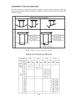
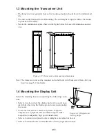
1-7
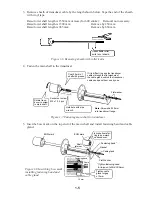
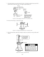
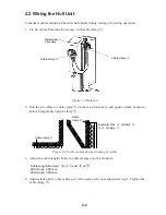
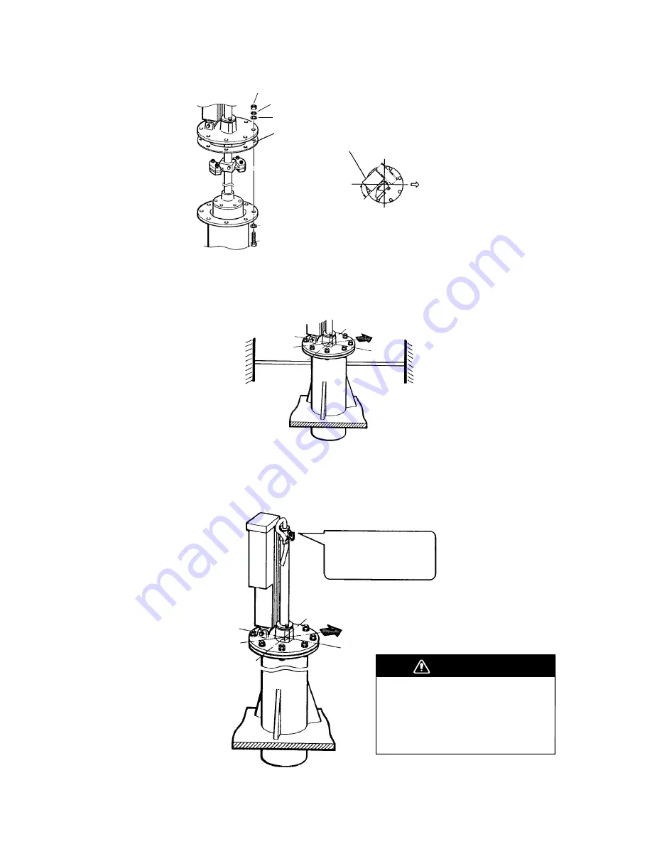
9. Fasten the hull unit to the retraction tank. Orient it so the ship’s fore-aft line crosses the front
panel of the raise/lower drive assy. at an angle of approximately 45
°
.
Raise/lower
drive assy
M20 Flat washer
Gasket
M20 Flat washer
M20 x 80
Orient the hull unit as shown.
This will reduce shock and
vibration, caused by ship's
pitching and rolling, at the
raise/lower drive assy.
BOW
M20 Nut
M20 Spring washer
Figure 1-12 Fastening the hull unit to the retraction tank
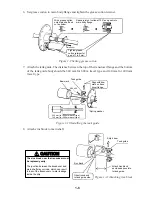
10. Fix anti-vibration stays to the retraction tank.
Anti-vibration
stay
Figure 1-13 Fixing anti-vibration stays to retraction tank
11. Orient the main shaft so that the bow mark faces ship’s bow and fix it securely with the shaft
retainer.
Loosen shaft retainer
and rotate main shaft
so the bow mark on
it faces ship's bow.
Bow mark
Ship's bow
Figure 1-14 Orienting the main shaft
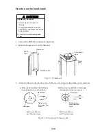
WARNING
POSSIBILITY OF WATER LEAKAGE
To prevent loss of main shaft of the hull
unit and water leakage tighten bolts fixing
shaft retainer for torque of 2000-2500 N
•
cm and tighten fastening band for torque
600-800 N
•
cm.
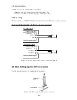
Summary of Contents for CSH-7
Page 1: ...COLOR SCANNING SONAR MODEL CSH 7 ...
Page 4: ...ii ...
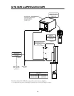
Page 6: ...iv SYSTEM CONFIGURATION ...
Page 15: ...1 8 ...
Page 16: ...1 9 ...
Page 35: ......
Page 36: ......
Page 37: ......
Page 38: ......
Page 39: ......
Page 40: ......
Page 41: ......
Page 42: ......
Page 43: ......
Page 44: ......
Page 45: ......
Page 46: ......
Page 47: ......
Page 48: ......
Page 49: ......
Page 50: ......
Page 51: ......
Page 52: ......
Page 53: ......
Page 54: ......
Page 55: ......
Page 56: ......
Page 57: ......
Page 58: ......


