
5-1
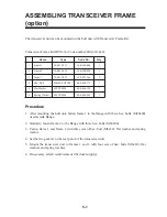
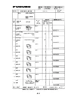
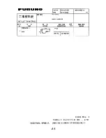
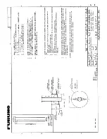
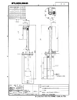
ASSEMBLING TRANSCEIVER FRAME
(option)
The transceiver unit can be mounted on the hull unit with Transceiver Frame Kit.
Transceiver Frame Kit OP10-14 (Code number:006-630-640)
e
m
a
N
e
p
y
T
.
o
N
e
d
o
C
y
t
Q
1
1
e
m
a
r
F
1
5
0
3
-
1
6
0
-
0
1
0
4
8
-
0
5
2
-
0
0
1
1
2
2
e
m
a
r
F
2
5
0
3
-
1
6
0
-
0
1
0
5
8
-
0
5
2
-
0
0
1
1
3
t
e
k
s
a
G
3
5
0
3
-
1
6
0
-
0
1
0
6
3
-
3
5
2
-
0
0
1
2
4
t
l
o
B
.
x
e
H
4
0
3
S
U
S
0
2
x
8
M
1
7
7
-
8
6
8
-
0
0
0
7
5
r
e
h
s
a
W
t
a
l
F
4
0
3
S
U
S
8
M
0
3
1
-
4
6
8
-
0
0
0
7
6
r
e
h
s
a
W
g
n
i
r
p
S
4
0
3
S
U
S
8
M
2
6
2
-
4
6
8
-
0
0
0
7
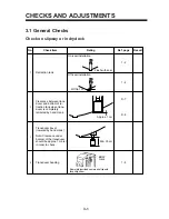
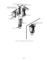
Procedure
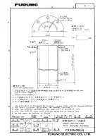
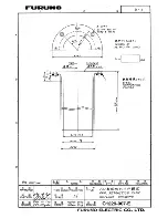
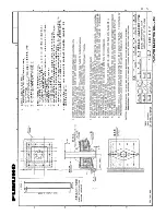
1. After mounting the hull unit, fasten frame 1 to the flange with three hex. bolts (M20x80)
used at tank flange.
2. Similairy, fasten frame 2 to the flange with three hex. bolts (M20x80).
3. Fasten frame 1 and frame 2 with three sets of hex. bolt (M8x20), flat washer and spring
washer.
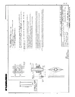
4. Set the two gaskets to the rear panel of the transceiver unit.
5. Mount the transceiver unit to frames 1 and 2 with four sets of hex. bolts (M8x20), flat
washers and spring washers.
6. If necessary, attach reinforcement ribs (local supply).
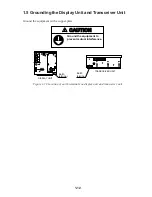
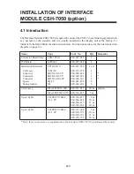
Summary of Contents for CSH-7
Page 1: ...COLOR SCANNING SONAR MODEL CSH 7 ...
Page 4: ...ii ...
Page 6: ...iv SYSTEM CONFIGURATION ...
Page 15: ...1 8 ...
Page 16: ...1 9 ...
Page 35: ......
Page 36: ......
Page 37: ......
Page 38: ......
Page 39: ......
Page 40: ......
Page 41: ......
Page 42: ......
Page 43: ......
Page 44: ......
Page 45: ......
Page 46: ......
Page 47: ......
Page 48: ......
Page 49: ......
Page 50: ......
Page 51: ......
Page 52: ......
Page 53: ......
Page 54: ......
Page 55: ......
Page 56: ......
Page 57: ......
Page 58: ......


