


iii
TABLE OF CONTENTS
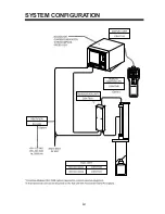
SYSTEM CONFIGURATION
.................................................................................. iii
MOUNTING
1.1 General Mounting and Handling Considerations ............................................................ 1-1
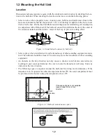
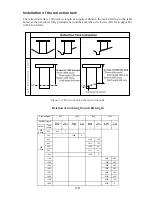
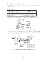
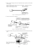
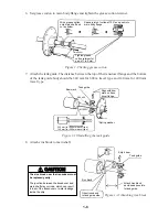
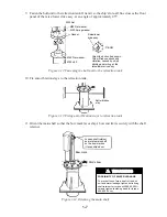
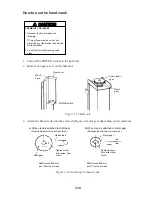
1.2 Mounting the Hull Unit ...................................................................................................1-2
1.3 Mounting the Transceiver Unit ...................................................................................... 1-11
1.4 Mounting the Display Unit ............................................................................................ 1-11
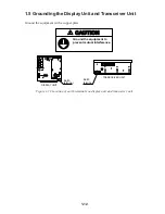
1.5 Grounding the Display Unit and Transceiver Unit ........................................................1-12
WIRING
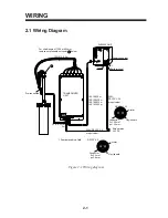
2.1 Wiring Diagram ...............................................................................................................2-1
2.2 Wiring the Hull Unit ........................................................................................................ 2-2
2.3 Wiring the Transceiver Unit............................................................................................. 2-3
2.4 Wiring the Display Unit ...................................................................................................2-4
2.5 Synchronizing Transmission with Other Equipment .......................................................2-5
2.6 How to Unplug the XH Connector .................................................................................. 2-7
CHECKS AND ADJUSTMENTS
3.1 General Checks ................................................................................................................ 3-1
3.2 Heading Alignment .......................................................................................................... 3-3
3.3 Sea Trial ...........................................................................................................................3-4
INSTALLATION OF INTERFACE MODULE CSH-7050 (option)
4.1 Introduction ..................................................................................................................... 4-1
4.2 Installation .......................................................................................................................4-2
ASSEMBLING TRANSCEIVER FRAME (Option)
.................................... 5-1
DRAWINGS
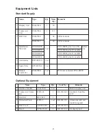
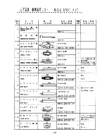
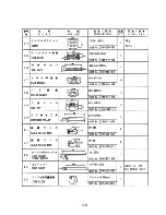
Equipment Lists .................................................................................................................... A-1
Outline Drawings .................................................................................................................. D-1
Interconnection Diagram ...................................................................................................... S-1
Schematic Diagram ............................................................................................................... S-2
Summary of Contents for CSH-7
Page 1: ...COLOR SCANNING SONAR MODEL CSH 7 ...
Page 4: ...ii ...
Page 6: ...iv SYSTEM CONFIGURATION ...
Page 15: ...1 8 ...
Page 16: ...1 9 ...
Page 35: ......
Page 36: ......
Page 37: ......
Page 38: ......
Page 39: ......
Page 40: ......
Page 41: ......
Page 42: ......
Page 43: ......
Page 44: ......
Page 45: ......
Page 46: ......
Page 47: ......
Page 48: ......
Page 49: ......
Page 50: ......
Page 51: ......
Page 52: ......
Page 53: ......
Page 54: ......
Page 55: ......
Page 56: ......
Page 57: ......
Page 58: ......