3-8
3.3 Mounting the Transmitter Unit
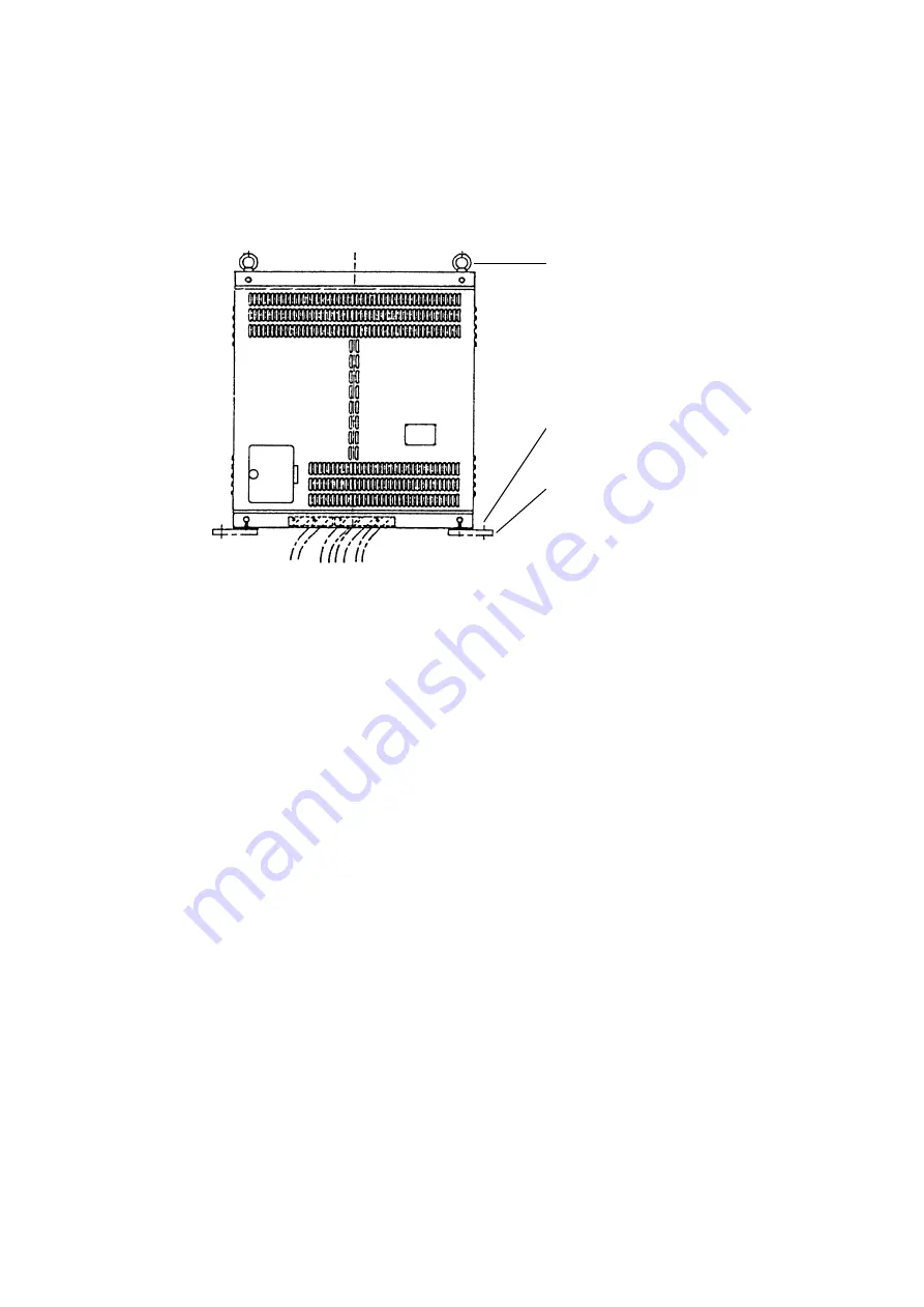
The transmitter unit can be mounted with or without mounting legs. For use without mounting
legs remove them and use inside mounting holes.
Reinforce the transmitter unit against vibration by stays extending from the eyebolts on the top
of the unit.
Attach stay to
this eye bolt.
Mounting leg for
outside leg mounting
For mounting without legs,
remove legs and use inside
holes for mounting.
Figure 3-11 Transmitter unit
3.4 Mounting the Power Unit
The power unit can be installed in any dry, well-ventilated place.
3.5 Mounting the Interface Unit
The interface unit connects with several navigation and fishing equipment, so determine the
installation site with the wiring to them taken into account. Furthermore, the unit incorporates
a data selector and self-check switch, therefore select a place where they can be easily operated.
3.6 Mounting the FNZ Joint Box
The FNZ joint box interchanges both Tx trigger and sounder marker pulses from the echo
sounder and the net sonde. Therefore, install it as close as possible to the net-sonde indicator.
Summary of Contents for CSH-83
Page 1: ...COLOR SCANNING SONAR MODEL CSH 83 84 Back ...
Page 6: ...This page is intentionally left blank ...
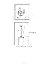
Page 11: ...3 2 Heater Heat insulator Figure 3 2 Typical sonar compartment ...
Page 68: ...A 10 ...
Page 77: ...A 19 ...
Page 78: ...A 20 ...
Page 79: ...A 21 ...
Page 80: ...A 22 ...
Page 81: ...A 23 ...
Page 82: ...A 24 ...
Page 83: ...A 25 ...
Page 84: ...A 26 ...
Page 85: ...D 1 ...
Page 86: ...D 2 ...
Page 87: ...Y Hatai D 3 ...
Page 88: ...D 4 ...
Page 89: ...Oct 31 03 D 5 ...
Page 90: ...Dec 10 02 D 6 ...
Page 91: ...D 7 ...
Page 92: ...D 8 ...
Page 93: ...D 9 ...
Page 94: ...D 10 ...
Page 95: ...D 11 ...
Page 96: ...D 12 ...
Page 97: ...D 13 ...
Page 98: ...D 14 ...
Page 99: ...D 15 ...
Page 100: ...D 16 ...
Page 101: ...D 17 ...
Page 102: ...D 18 ...
Page 103: ...D 19 ...
Page 104: ...D 20 ...

