ii
TABLE OF CONTENTS
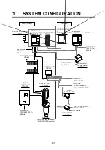
1. SYSTEM CONFIGURATION .........................................................
1-1
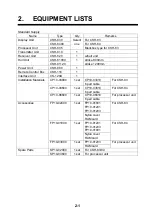
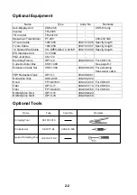
2. EQUIPMENT LISTS ......................................................................
2-1
3. MOUNTING THE EQUIPMENT
3.1 Mounting the Hull Unit and Receiver Unit ................................................................ 3-1
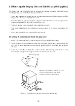
3.2 Mounting the Display Unit and Sub-Display Unit (option) .......................................3-7
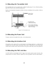
3.3 Mounting the Transmitter Unit ...................................................................................3-8
3.4 Mounting the Power Unit ...........................................................................................3-8
3.5 Mounting the Interface Unit .......................................................................................3-8
3.6 Mounting the FNZ Joint Box ..................................................................................... 3-8
3.7 Grounding the Equipment .......................................................................................... 3-9
4. WIRING
4.1 Cable Configuration ...................................................................................................4-1
4.2 How to Use the Crimping Tool and Pin Extractor ..................................................... 4-2
4.3 Location of Connectors .............................................................................................. 4-3
4.4 Cable Fabrication and Connector Assembling in Display and Interface Units .......... 4-4
4.5 Cable Fabrication and Connector Assembling in Power Unit .................................... 4-7
4.6 Cable Fabrication and Connector Assembling in Transmitter Unit ...........................4-9
4.7 Cable Fabrication and Connector Assembling in Hull Unit (incl. receiver unit) ..... 4-11
4.8 Connection of Transducer Cables ............................................................................4-13
4.9 Connection of Interface Unit ....................................................................................4-14
4.10 Connection of Sub-Display Unit (option) .............................................................. 4-19
4.11 Connection of Remote Display Unit (option) ........................................................4-20
4.12 Synchronizing Transmission with Other Sonars or Echo Sounders .......................4-21
4.13 Interlocking Operation with Other Sonars .............................................................4-22
5. CHANGING POWER SPECIFICATIONS
6. INSTALLATION OF FRP RETRACTION TANK
6.1 Before Beginning the Installation .............................................................................. 6-1
6.2 Installation of the FRP Retraction Tank ..................................................................... 6-1
Summary of Contents for CSH-83
Page 1: ...COLOR SCANNING SONAR MODEL CSH 83 84 Back ...
Page 6: ...This page is intentionally left blank ...
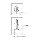
Page 11: ...3 2 Heater Heat insulator Figure 3 2 Typical sonar compartment ...
Page 68: ...A 10 ...
Page 77: ...A 19 ...
Page 78: ...A 20 ...
Page 79: ...A 21 ...
Page 80: ...A 22 ...
Page 81: ...A 23 ...
Page 82: ...A 24 ...
Page 83: ...A 25 ...
Page 84: ...A 26 ...
Page 85: ...D 1 ...
Page 86: ...D 2 ...
Page 87: ...Y Hatai D 3 ...
Page 88: ...D 4 ...
Page 89: ...Oct 31 03 D 5 ...
Page 90: ...Dec 10 02 D 6 ...
Page 91: ...D 7 ...
Page 92: ...D 8 ...
Page 93: ...D 9 ...
Page 94: ...D 10 ...
Page 95: ...D 11 ...
Page 96: ...D 12 ...
Page 97: ...D 13 ...
Page 98: ...D 14 ...
Page 99: ...D 15 ...
Page 100: ...D 16 ...
Page 101: ...D 17 ...
Page 102: ...D 18 ...
Page 103: ...D 19 ...
Page 104: ...D 20 ...


