1. INSTALLATION
1-5
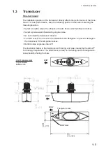
Transom mount
For a vessel with an inboard engine, the transducer cannot be installed aft of the pro-
peller screw because of the turbulence created by the propeller ahead of the transduc-
er. Determine the mounting location considering the guidelines shown below and the
instructions on page AP-8.
• Select a location as far as possible from the propeller screw.
• Select a location where the propeller screw is not within 120° of the beam range of
the transducer.
Be sure to select the location considering these guidelines, to prevent echo noise on
the display.
The illustration below was created by the Airmar
®
Technology Corporation.
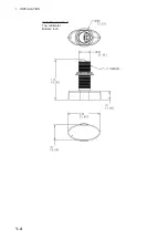
Unit of measurement
Top: millimeter
Bottom: inch
Summary of Contents for DFF-3D
Page 1: ...MULTI BEAM SONAR DFF 3D OPERATOR S MANUAL www furuno com Model ...
Page 10: ...SYSTEM CONFIGURATION viii This page is intentionally left blank ...
Page 14: ...1 INSTALLATION 1 4 Unit of measurement Top millimeter Bottom inch ...
Page 16: ...1 INSTALLATION 1 6 This page is intentionally left blank ...
Page 36: ...3 INITIAL SETTINGS 3 10 This page is intentionally left blank ...
Page 54: ...4 OPERATION 4 18 This page is intentionally left blank ...
Page 68: ...APPENDIX 4 INSTALLATION OF TRANSDUCER TM54 AP 12 This page is intentionally left blank ...
Page 71: ...D 1 20 Sep 2016 H MAKI 20 Sep 2016 H MAKI 20 Sep 2016 H MAKI 20 Sep 2016 H MAKI ...
Page 74: ...INDEX IN 2 Z Zoom display 4 8 ...


