3. INITIAL SETTINGS
3-4
3.3
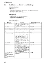
Multi Function Display Initial Settings
How to open the menu
NavNet TZtouch
:
1. Push the Home button (or tap the home icon) to display the menu icon bar.
2. Select [Menu], [Multibeam Sonar].
3. Enter initial settings referring to the table below.
NavNet TZtouch2
:
1. Tap the Home icon to go to the home screen.
2. Select [Settings], [Multibeam Sonar].
3. Enter initial settings referring to the tables that follow.
Multibeam Sonar menu
Menu item
Description
Options (setting range)
[Transducer Draft]
Set the distance between the transducer
and the draft line to show the distance
from the sea surface.
[0.0m] to [99.9m]
[Salt Water]
Select [ON] to use this equipment in salt
water.
[OFF], [ON]
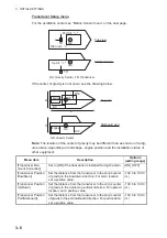
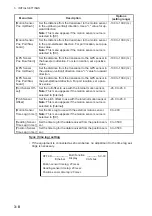
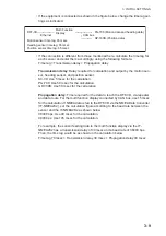
[Transducer Setup]
Set page 3-6 “Transducer Setup”.
[Transmission Power Au-
to]
Turn on to automatically adjust trans-
mission power to display the seabed
echo properly.
[OFF], [ON]
[Transmission Power]
Set the TX power level manually. Inter-
ference may appear on your display
when a sonar of the same frequency as
yours is being operated on a vessel
nearby. When this occurs, lower the
transmission power and request the
nearby vessel to lower its sonar’s TX
power to reduce the interference. The
setting range is 0 to 10 and 10 is maxi-
mum power.
[0] to [10]
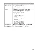
[External KP]
Select [ON] to synchronize with external
sounder’s keying pulse.
[ON], [OFF]
[Bottom Level]
The default bottom level setting (0) de-
termines that two strong echoes re-
ceived in sequence are seabed echoes.
If the depth indication is not stable in the
default setting, adjust the bottom level
here. If you can not discriminate the fish
near the seabed from the seabed echo,
increase the bottom level.
[-40] to [40]
[Auto Gain Offset (Multi
Sounder)],
[Auto Gain Offset (Side
Scan)],
[Auto Gain Offset (Cross
Section)]
In the auto mode, lower or raise the gain
as necessary.
[-5] to [5]
Summary of Contents for DFF-3D
Page 1: ...MULTI BEAM SONAR DFF 3D OPERATOR S MANUAL www furuno com Model ...
Page 10: ...SYSTEM CONFIGURATION viii This page is intentionally left blank ...
Page 14: ...1 INSTALLATION 1 4 Unit of measurement Top millimeter Bottom inch ...
Page 16: ...1 INSTALLATION 1 6 This page is intentionally left blank ...
Page 36: ...3 INITIAL SETTINGS 3 10 This page is intentionally left blank ...
Page 54: ...4 OPERATION 4 18 This page is intentionally left blank ...
Page 68: ...APPENDIX 4 INSTALLATION OF TRANSDUCER TM54 AP 12 This page is intentionally left blank ...
Page 71: ...D 1 20 Sep 2016 H MAKI 20 Sep 2016 H MAKI 20 Sep 2016 H MAKI 20 Sep 2016 H MAKI ...
Page 74: ...INDEX IN 2 Z Zoom display 4 8 ...


