3. INITIAL SETTINGS
3-6
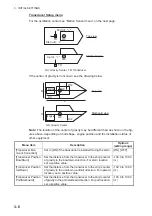
Transducer Setup menu
For the oscillation center see “Motion Sensor menu” on the next page.
If the center of gravity is not known, see the drawing below.
Note:
The location of the center of gravity may be different than as shown in the fig-
ures above, depending on hull shape, engine position and the installation status of
other equipment.
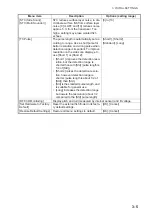
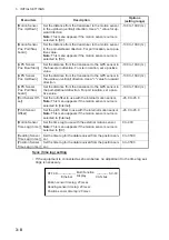
Menu item
Description
Options
(setting range)
[Transducer Mis-
mount Correction]
Set to [ON] if the transducer is installed facing the stern. [ON], [OFF]
[Transducer Position
Bow/Stern]
Set the distance from the transducer to the ship’s center
of gravity in the bow/stern direction. For stern location,
set a positive value.
-100.0 to 100.0
(m)
[Transducer Position
Up/Down]
Set the distance from the transducer to the ship’s center
of gravity in the up/down (vertical) direction. For upward
location, set a positive value.
-100.0 to 100.0
(m)
[Transducer Position
Port/Starboard]
Set the distance from the transducer to the ship’s center
of gravity in the port/starboard direction. For port location,
set a positive value.
-100.0 to 100.0
(m)
GC
TD
GC
TD
Up dir.: "+"
Stern dir.: “+”
Port dir.: "+"
Top view
Starboard view
GC:
Gravity Center
, TD: Transducer
GC
GC
W
W/2
Top view
Starboard view
Engine
H
H/2
L/3
L
GC:
Gravity Center
Engine
Summary of Contents for DFF-3D
Page 1: ...MULTI BEAM SONAR DFF 3D OPERATOR S MANUAL www furuno com Model ...
Page 10: ...SYSTEM CONFIGURATION viii This page is intentionally left blank ...
Page 14: ...1 INSTALLATION 1 4 Unit of measurement Top millimeter Bottom inch ...
Page 16: ...1 INSTALLATION 1 6 This page is intentionally left blank ...
Page 36: ...3 INITIAL SETTINGS 3 10 This page is intentionally left blank ...
Page 54: ...4 OPERATION 4 18 This page is intentionally left blank ...
Page 68: ...APPENDIX 4 INSTALLATION OF TRANSDUCER TM54 AP 12 This page is intentionally left blank ...
Page 71: ...D 1 20 Sep 2016 H MAKI 20 Sep 2016 H MAKI 20 Sep 2016 H MAKI 20 Sep 2016 H MAKI ...
Page 74: ...INDEX IN 2 Z Zoom display 4 8 ...

