AP-4
APPENDIX 3 INSTALLATION OF
TRANSDUCER B54
This appendix provides a copy of the installation instructions and Installation supplement for the
AIRMAR
®
Technology Corporation Transducer B54. For the latest version of these instructions,
see the materials provided with the transducer.
17
-6
21
-0
1-
rev. 02
01
/06
/17
INSTALLATION INSTRUCTIONS
WARNING
Installation of the anti-rotation bolt is mandatory!
The anti-rotation bolt
holds the fairing firmly in place. Failure to install the anti-
rotation bolt may result in the fairing rotating while the boat is underway. The
effect may be violen
t movement and loss of steering. This could result in serious
injury or death to passengers and/or damage to the boat or other property.
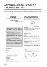
B54 Depth Transducer
with
Temperature Sensor &
High-Performance Fairing
Applications
• Bronze transducer recommended for fiberglass or wood hull.
• Maximum deadrise angle of 24°
Tools & Materials
Safety goggles
Dust mask
Ear plugs
Electric drill
Drill bits and hole saws:
Pilot hole
3mm or 1/8"
m
m
1
5
4
5
B
or 2"
Anti-rotation bolt
11mm or 7/16"
Angle finder
Band saw (sharp blade)
Rasp
or power tool
Sandpaper
Mild household detergent
or weak solvent (such as alcohol)
Marine sealant (suitable for below waterline)
Slip-joint pliers
Mallet
Grommets (some installations)
Cable ties
Water-based anti-fouling paint (mandatory in salt water )
Installation in a cored fiberglass hull (see page 4)
Hole saw for hull interior—transducer
min. 65mm or 2-5/8"
Drill bit for hull interior—anti-rotation bolt
min. 25mm or 1"
Cylinders, wax, tape, and casting epoxy
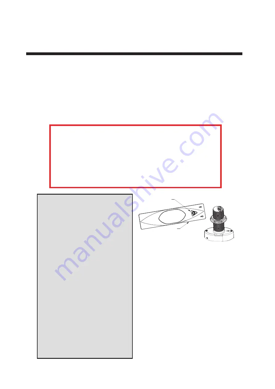
triangular
cutting
recess for
anti-rotation bolt
guide
Follow the precautions below for optimal product
performance and to reduce the risk of property damage,
personal injury, and/or death.
WARNING
: A High-Performance Fairing must be installed
following the installation instructions that accompany the fairing.
WARNING
: Always wear safety goggles, a dust mask, and
ear plugs when installing.
WARNING
: The fairing must be installed parallel to the keel
to ensure proper boat handling.
WARNING
: Do not install a fairing that has been mis-cut.
Replace it.
• Cutting the fairing at an angle greater than the maximum
allowed will cut into the transducer and/or bolt pocket,
thus weakening the fairing.
• Do not allow any gap between the fairing and the hull that is
greater than 3mm (1/8"). When the boat is underway,
water will enter any gaps and push against the fairing with
considerable force, possibly rotating it.
WARNING
: Immediately check for leaks when the boat is
placed in the water. Do not leave the boat unchecked for
more than three hours. Even a small leak may allow
considerable water to accumulate.
CAUTION
: Never mount a bronze transducer in a metal hull,
because electrolytic corrosion will occur.
CAUTION
: Never install a bronze transducer on a vessel
with a positive ground system.
CAUTION
: Never pull, carry, or hold the transducer by the
cable as this may sever internal connections.
CAUTION
: Never strike the transducer.
CAUTION
: Do not over-tighten the hull nut and the nut on
the anti-rotation bolt, crushing the fairing and/or hull.
CAUTION
: The transducer and the yellow triangular plug
must be flush with the fairing for smooth water flow under the
transducer.
CAUTION
: Never use solvents. Cleaner, fuel, sealant, paint,
and other products may contain solvents that can damage
plastic parts, especially the transducer’s face.
IMPORTANT
: Read the instructions completely before
proceeding with the installation. These instructions supersede
any other instructions in your instrument manual if they differ.
Summary of Contents for DFF-3D
Page 1: ...MULTI BEAM SONAR DFF 3D OPERATOR S MANUAL www furuno com Model ...
Page 10: ...SYSTEM CONFIGURATION viii This page is intentionally left blank ...
Page 14: ...1 INSTALLATION 1 4 Unit of measurement Top millimeter Bottom inch ...
Page 16: ...1 INSTALLATION 1 6 This page is intentionally left blank ...
Page 36: ...3 INITIAL SETTINGS 3 10 This page is intentionally left blank ...
Page 54: ...4 OPERATION 4 18 This page is intentionally left blank ...
Page 68: ...APPENDIX 4 INSTALLATION OF TRANSDUCER TM54 AP 12 This page is intentionally left blank ...
Page 71: ...D 1 20 Sep 2016 H MAKI 20 Sep 2016 H MAKI 20 Sep 2016 H MAKI 20 Sep 2016 H MAKI ...
Page 74: ...INDEX IN 2 Z Zoom display 4 8 ...


