background image

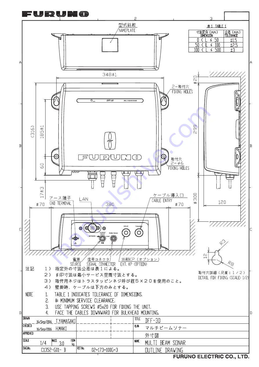
D-1

20/Sep/2016 H.MAKI

20/Sep/2016 H.MAKI

20/Sep/2016 H.MAKI

20/Sep/2016 H.MAKI

Summary of Contents for DFF-3D

Page 1: ...MULTI BEAM SONAR DFF 3D OPERATOR S MANUAL www furuno com Model ...

Page 2: ...7KH SDSHU XVHG LQ WKLV PDQXDO LV HOHPHQWDO FKORULQH IUHH 85812 XWKRUL HG LVWULEXWRU HDOHU VKLKDUD FKR 1LVKLQRPL D 3 1 3ULQWHG LQ DSDQ OO ULJKWV UHVHUYHG 2 7 3XE 1R 20 0 ...

Page 3: ... or service marks of their respective holders How to discard this product Discard this product according to local regulations for the disposal of industrial waste For disposal in the USA see the homepage of the Electronics Industries Alliance http www eiae org for the correct method of disposal How to discard a used battery Some FURUNO products have a battery ies To see if your product has a batte...

Page 4: ...instructions before attempting to install or operate the equipment WARNING WARNING Do not open the equipment Only qualified personnel can work inside the equipment Do not disassemble or modify the equipment Fire electrical shock or serious injury can result Turn off the power immediately if the equipment is emitting smoke or fire Fire or electrical shock can result if the power is left on Turn off...

Page 5: ...mpass safe distances shown below to prevent interference to a magnetic compass Standard compass 1 25 m Steering compass 0 80 m WARNING WARNING Do not work inside the equipment unless qualified to do so Electrical shock can occur Turn off the power before beginning the installation Fire or electrical shock can result if the power is on Be sure no water leaks at the mounting location for the transdu...

Page 6: ... between TX and STBY 4 6 4 3 2 How to change echo color 4 6 4 3 3 How to show or hide the scale box 4 6 4 3 4 Availability of points and event marks registration and go to a point 4 7 4 4 Cross Section Display Operations 4 8 4 4 1 How to switch between TX and STBY 4 8 4 4 2 How to show or hide the grid 4 8 4 4 3 Zoom display 4 8 4 4 4 How to smooth echoes distance 4 8 4 4 5 How to smooth echoes ti...

Page 7: ... go to a point 4 17 5 MAINTENANCE TROUBLESHOOTING 5 1 5 1 Maintenance 5 1 5 2 How to Replace the Fuse 5 2 5 3 How to Restore Default Settings 5 2 APPENDIX 1 MENU TREE AP 1 APPENDIX 2 JIS CABLE GUIDE AP 3 APPENDIX 3 INSTALLATION OF TRANSDUCER B54 AP 4 APPENDIX 4 INSTALLATION OF TRANSDUCER TM54 AP 8 SPECIFICATIONS SP 1 INDEX IN 1 ...

Page 8: ... properly Please carefully read and follow the recommended procedures for installa tion operation and maintenance Thank you for considering and purchasing FURUNO Features The DFF 3D Multi Beam Sonar provides high definition images of underwater conditions and the seabed Connected to the NavNet TZtouch NavNet TZtouch2 Multi Function Display the DFF 3D distributes images of the undersea throughout t...

Page 9: ...URATION MULTI BEAM SONAR DFF 3D NavNet TZtouch TZT9 14 BB NavNet TZtouch2 TZTL12F 15F 12 24 VDC Rectifier PR 62 100 110 220 230 VAC 1ø 50 60 Hz External KP Transducer B54 or TM54 Optional or local supply Standard supply ...

Page 10: ...SYSTEM CONFIGURATION viii This page is intentionally left blank ...

Page 11: ...740 1 set Fuses Installation Materials CP02 09400 000 029 992 1 set Power cable assy 3 5 m LAN cable assy 5 m Self tapping screws Conductive tape Name Type Code No Remarks Connector Kit for TX Sync OP02 86 001 205 780 Cable Assembly MOD Z072 020 001 167 880 10 2 m for HUB 101 Cable Assembly MOD Z072 100 001 167 900 10 10 m for HUB 101 Rectifier PR 62 000 013 484 100 VAC 000 013 485 110 VAC 000 013...

Page 12: ...e unit away from electromagnetic field generating equipment such as mo tors and generators Observe the minimum recommended maintenance space shown in the outline drawing at the back of this manual Also leave slack in cables for maintenance and servicing ease A magnetic compass may receive interference if it is placed too close to this unit Observe the compass safe distances noted in the safety ins...

Page 13: ... Select a place least influenced by engine noise Do not install the transducer inboard For FRP vessel do not cover the transducer with fiberglass to prevent damage to the transducer if the temperature rises Bottom slope angle less than 24 The illustration below is the transducer with fairing and was created by the Airmar Technology Corporation The BOW mark arrow on the fairing and the triangular r...

Page 14: ...1 INSTALLATION 1 4 Unit of measurement Top millimeter Bottom inch ...

Page 15: ...sidering the guidelines shown below and the instructions on page AP 8 Select a location as far as possible from the propeller screw Select a location where the propeller screw is not within 120 of the beam range of the transducer Be sure to select the location considering these guidelines to prevent echo noise on the display The illustration below was created by the Airmar Technology Corporation U...

Page 16: ...1 INSTALLATION 1 6 This page is intentionally left blank ...

Page 17: ...ship s ground to prevent interference to the sounder picture Make the length of the wire as short as possible For FRP vessels install a ground plate approx 20 cm by 30 cm on the outside of the hull bottom and connect the ground wire there Ground wire IV 2 sq MOD Z072 050 5 m option 2 10 m TZT9 TZT14 TZTBB TZTL12F TZTL15F GROUND MJ A3SPF0013 035C 3 5 m External KP Transducer B54 or TM54 Power suppl...

Page 18: ...Fabricate the cable as shown in the procedure below then connect it inside the unit with a WAGO connector 1 Fabricate the cable as shown below Note Keep the recommended lengths to prevent noise in the cable 2 Remove the outer cover 3 Unfasten four screws to remove the inner chassis cover Unit mm Sheath x9 x9 Shield Shield 110 6 80 Wrap with vinyl tape width 30 mm Wrap shield with conductive tape S...

Page 19: ...Unfasten two screws to remove the clamping plate for the transducer cable 7 Pass the transducer cable through the sealing nut unfastened at step 5 then pass the cable through the super gland and into the unit WAGO connector opener WAGO connector TB1 TB2 TB3 Super gland Sealing nut Unfasten these screws to remove the clamping plate ...

Page 20: ...le such that its conductive tape lies beneath the clamping plate Hold the clamping plate in place with your fingers then fasten the plate 11 Fasten the sealing nut into the super gland The gap between the sealing nut end and the super gland should be 2 mm The fastening torque is 1 8 2 0 N m 12 Reattach the inner and outer covers How to connect cable to WAGO connector Push down Opener WAGO connecto...

Page 21: ...h of the wires of the PH connector assembly supplied 100 mm b Remove the sheath from the cores 10 mm c Fold back the cores in half Attach crimp on lug NCW 1 25 supplied to each core d Remove the armor 300 mm and cut off the vinyl sheath 130 mm Name Type Code No Qty Remarks Upset UI Screw B M4u20 000 163 756 10 2 Super Gland MGB20M 12B 000 177 248 10 1 PH Connector Assembly 02 1097 4P 001 206 000 1...

Page 22: ...a tions shown Pass the cable through its cable gland Fix the cable with the ca ble clamp and sealing nut 2 Remove the outer cover 3 Loosen four screws to remove the inner chassis cover 4 Detach the protective sheet from the location for the external KP cable Approx 5 mm This part is fixed with the sealing nut Lay this part in the cable clamp Armor Vinyl sheath NCW 1 25 Wrap with vinyl tape Wrap wi...

Page 23: ...the super gland to the unit 7 Fasten the sealing nut into the super gland The gap between the sealing nut end and the super gland should be 4 mm The fastening torque is 1 8 2 0 N m 8 Position the cable so its vinyl sheath lies in the cable clamp Use the supplied ca ble clamping plate to secure the cable Lock nut Super gland Cable for external KP MPYC SLA 4 Sealing nut 4 mm Secure cable with cable ...

Page 24: ...rough the cable saddle Make sure the crimp connectors are not clamped by the cable saddle Note 2 Confirm that the direction of the clamping plate is as shown below 10 Attach the supplied EMI core GRFC 10 to the cable for the external KP approx 10 mm from the super gland 11 Reattach the inner and outer covers J9 Clamp Lay vinyl sheath in the cable clamp and secure the cable with the cable clamp Mak...

Page 25: ...rder shown in the figure below Connect the cable to the LAN connector Note the orientation of the sealing insert when passing it onto the cable Push the cable into the slit in the sealing insert 4 Set the sealing insert and clamping claw into the sealing nut then tighten the nut How to detach clamping claw Hold the clamping claw seal assy as shown left with the teeth of the clamping claw toward yo...

Page 26: ... nut and the super gland shall be 3 mm The fastening torque for the sealing nut is 1 8 2 0 Nm How to disconnect the LAN cable Loosen the two screws on the gland to access the cable s connector A lock washer is fitted to the gland so the screws cannot be unfastened completely 3 mm Screw 2 pcs Gland ...

Page 27: ... and S3 should be left in the default position OFF DIP switch S2 DIP switch S3 1 2 3 4 5 6 7 8 OFF 1 2 3 4 OFF WARNING Do not open the equipment unless totally familiar with electrical circuits Only qualified personnel are permitted to work inside the equipment S2 S3 ...

Page 28: ...IP address assignment OFF Fixed static IP address Set the IP address with switch 2 ON IP address assigned automatically 2 IP address no Effective when 1 segment is OFF See the table below for IP address Currently this function has no use 3 Restore default settings other than LAN See section 5 3 4 Restore ALL default settings See section 5 3 5 6 Keep these switches in the OFF position 7 No use 8 No...

Page 29: ...n the cover of the DFF 3D lights or flashes according to equipment state as described in the table below LED state and meaning LED state Meaning Lit continuously Standby state If no signal is received via LAN for more than 10 minutes the equipment automatically goes into standby to lessen power consumption Blinking every two seconds Normal operation 㻸㻱㻰 ...

Page 30: ...trans mission power to display the seabed echo properly OFF ON Transmission Power Set the TX power level manually Inter ference may appear on your display when a sonar of the same frequency as yours is being operated on a vessel nearby When this occurs lower the transmission power and request the nearby vessel to lower its sonar s TX power to reduce the interference The setting range is 0 to 10 an...

Page 31: ...tection reso lution but the detection range is shorter than with Std pulse length is 1 4 of Std Short 2 raises the detection resolu tion however detection range is shorter pulse length is about 1 2 of Std than Std Std is the standard pulse length and is suitable for general use Long increases the detection range but lowers the resolution about 1 2 compared to the Std pulse length Short1 Short2 Sta...

Page 32: ...Bow Stern Set the distance from the transducer to the ship s center of gravity in the bow stern direction For stern location set a positive value 100 0 to 100 0 m Transducer Position Up Down Set the distance from the transducer to the ship s center of gravity in the up down vertical direction For upward location set a positive value 100 0 to 100 0 m Transducer Position Port Starboard Set the dista...

Page 33: ...nu item Description Options setting range Motion Sensor Source Select the sensor connected to you NavNet TZtouch2 unit SC Internal OFF Motion Sensor Pos Bow Stern Set the distance from the transducer to the motion sensor in the bow stern direction For the stern side set a positive value Note This menu appears if the motion sensor source is selected to SC 100 to 100 0 m GC TD GC TD Up dir Stern dir...

Page 34: ...e for upward direction 100 to 100 0 m GPS Sensor Pos Port Star board Set the distance from the transducer to the GPS sensor in the port starboard direction For port location set a posi tive value 100 to 100 0 m Roll Sensor Off set Set the roll offset to use with the internal motion sensor Note This menu appears if the motion sensor source is selected to Internal 45 0 to 45 0 Pitch Sensor Offset Se...

Page 35: ...ta route For the multi function display connected by CAN bus use 15 msec for the calculation If NMEA data is fed to the DFF 3D via the NMEA Data Converter IF NMEA2K2 set the calculation figure according to the baud rate between the sensor and the IF NMEA2K2 as shown below 38400 bps Use 40 msec for the calculation 4800 bps Use 145 msec for the calculation For example the sensor feeding data to the ...

Page 36: ...3 INITIAL SETTINGS 3 10 This page is intentionally left blank ...

Page 37: ...ions The video display scrolls from the right to left with the passing of time The echoes appearing at the right edge of the display are the latest echoes Echoes from individual fish schools of fish and the seabed are shown With the gain set prop erly the distance to the seabed appears on the screen The gain clutter suppressor and TVG are adjusted according to the mode selected auto fishing or aut...

Page 38: ... the screen and the old est are at the bottom of the screen The side scan display is different from the other modes employed by this equipment it clearly displays the shape of echoes fish bed etc 19 5 Depth scale Depth scale Seabed echo Frequency Depth Port Port Starboard Starboard Downward Downward Max display depth Max display depth Depth Port direction echoes Starboard direction echoes Fish bed...

Page 39: ...des a 3D graphic of the past seabed and underwater echoes detected by your vessel The display can be used to detect schools of fish School of fish Seabed 㻻㼣㼚㻿㼔㼕㼜 㻻㼣㼚㻿㼔㼕㼜 STBD PORT Horizontal range scale Horizontal range scale Seabed Seabed Frequency Frequency Grid Grid Depth Depth scale Depth scale Max display depth Max display depth Transducer position Transducer position Underwater Underwater Do...

Page 40: ...le Beam or Triple Beam as required 4 Select Close to close the pop up menu 4 2 3 How to set the TX beam angle You can set the TX beam angle for the port starboard and downward beams 1 Tap the multi sounder display to show the pop up menu 2 Select Beam Angle 3 Set the beam angle as required 4 2 4 How to set the TX beam width You can set the TX beam width for the port starboard and downward beams 1 ...

Page 41: ...r NavNet TZtouch2 input PGN data The PGN data available is as shown below Latitude longitude data 129025 Position Rapid Update 129029 GNNS Position Data Heading data 127237 Heading Track Control 127250 Vessel Heading 130577 Direction Data Latitude Longitude Heading data YES Latitude Longitude YES Heading data NO Item Starboard Downward Port Point registration Yes Yes Yes Go to point Yes Yes Yes Ev...

Page 42: ... appears at the center of the screen when transmission is stopped 4 3 2 How to change echo color 1 Select Menu from the menu icon bar to show the menu 2 Select Multibeam Sonar 3 Select Echo Color 4 Select White Blue or Brown as required 5 Select Close to close the pop up menu 4 3 3 How to show or hide the scale box The scale box shown at the bottom left corner on the display shows depth current ra...

Page 43: ...ions below are available For NavNet TZtouch or NavNet TZtouch2 input PGN data The PGN data available is as shown below Latitude longitude data 129025 Position Rapid Update 129029 GNNS Position Data Heading data 127237 Heading Track Control 127250 Vessel Heading 130577 Direction Data Latitude Longitude Heading data YES Latitude Longitude YES Heading data NO Item Starboard Port Point registration Ye...

Page 44: ...oss section display to show the pop up menu 2 Select Grid to show the grid 4 4 3 Zoom display The seabed echo can be zoomed 1 Tap the cross section display to show the pop up menu 2 Select Zoom to zoom the seabed echo Select Zoom again to restore the nor mal display 4 4 4 How to smooth echoes distance If echoes are disconnected because of an undulating seabed change the setting to Low Medium or Hi...

Page 45: ...ed To compensate for this problem adjust the speed of sound Manual correction 1 Select Menu from the menu icon to show the menu 2 Select Multibeam Sonar 3 Select Sound Speed Correction then enter a correction The setting range is 200 to 200 4 Select Close to close the menu Automatic correction 1 Select Menu from the menu icon to show the menu 2 Select Multibeam Sonar 3 Select Temp based Correction...

Page 46: ...ne of the functions below are available For NavNet TZtouch or NavNet TZtouch2 input PGN data The PGN data available is as shown below Latitude longitude data 129025 Position Rapid Update 129029 GNNS Position Data Heading data 127237 Heading Track Control 127250 Vessel Heading 130577 Direction Data Latitude Longitude Heading data YES Latitude Longitude YES Heading data NO Item Cross section Point r...

Page 47: ... 5 2 How to move zoom in zoom out the viewpoint position How to move the viewpoint The viewpoint can be moved by dragging How to zoom in zoom out How to restore default view If you get lost in viewpoint or zoom you can restore the default view as follows 1 Tap the 3D sounder history display to show the pop up menu 2 Select Default View to show the depth frequency box 4 5 3 How to mark school of fi...

Page 48: ...echo If schools of fish or a fish reef are detected and displayed as the seabed echo adjust the strength of the seabed echo as shown below to correctly identify the seabed echo 1 Select Menu from the menu icon to show the menu 2 Select Multibeam Sonar 3 Select Seabed Echo Calibration Drag the slider bar to adjust The setting range is 15 to 15 A large figure helps distinguish bottom fish from the s...

Page 49: ...Color shading display Color shading can be applied to the seabed echo or schools of fish For the bottom display the bottom color can be multi tone or single tone and schools of fish can be shown in single tone or single color For the schools of fish display schools can be shown in multi tone or single tone and the bottom color is in a single tone 1 Tap the 3D sounder history display to show the po...

Page 50: ...ack Or White Pink Light Green Yellow Auto Seabed Shading Use automatic or manual seabed shading ON OFF Minimum Value Maximum Value Auto Seabed Shading Minimum Value Maximum Value Auto Fish Shading Seabed Color Fish Monochrome Color 0 m 50 m 0 m 50 m Classic Hue Gray Hue Minimum Value Maximum Value Auto Seabed Shading Minimum Value Maximum Value Auto Fish Shading Fish Color Seabed Monochrome Color ...

Page 51: ...a tion on the color bar scale to show the slider bar Drag the slider bar to set 0 to 1200 m Menu item Description Setting options Fish Color For setting multi tone or single tone Classic Hue Inverted Classic Hue Red Hue Blue Hue Green Hue Yellow Hue Fish Monochrome Color For setting single tone or single color Gray Hue Brown Hue Auto Fish Shading Use automatic or manual fish shading ON OFF Menu it...

Page 52: ...uto Fish Shading must be OFF to enter depth Alternatively tap the minimum value indica tion on the color bar scale to show the slider bar Drag the slider bar to set 0 to 1200 m Maximum Value Use the software keyboard to set the deepest depth to use Auto Fish Shading must be OFF to enter depth Alternatively tap the maximum value indica tion on the color bar scale to show the slider bar Drag the sli...

Page 53: ...r the multi function display input PGN data The PGN data available is as shown below Latitude longitude data 129025 Position Rapid Update 129029 GNNS Position Data Heading data 127237 Heading Track Control 127250 Vessel Heading 130577 Direction Data Latitude Longitude Heading data YES Latitude Longitude YES Heading data NO Item Fish Seabed Other than Fish or Seabed Point registration Yes Yes No Go...

Page 54: ...4 OPERATION 4 18 This page is intentionally left blank ...

Page 55: ...t problem Once a month Cabinet cleanliness Dust or dirt on the cabinet may be removed with a dry cloth Do not use chemical based cleaners to clean the cabinet they can remove markings and damage the cabinet Once a month Transducer Marine life on the transducer face will result in a gradual decrease in sensitivity Check the trans ducer face for cleanliness each time the boat is removed from the wat...

Page 56: ...et TZtouch NavNet TZtouch2 device You can restore all default settings or restore those other than LAN This procedure should only be performed by a suitably qualified FURUNO technician 1 Disconnect the power and LAN cables from the DFF 3D 2 Open the outer cover and shield cover Turn on the 3 or 4 switch of DIP Switch S2 as applicable 3 Restore default settings IP address etc except LAN related 4 R...

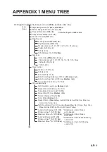
Page 57: ...er Off Low Medium High Terrain Shading 100 50 Color Mode Bottom Fish Seabed Color 1 Classic Hue Inverted Classic Hue Red Hue Blue Hue Green Hue Yellow Hue Fish Monochrome Color 1 Gray Hue Brown Hue Red Green Blue Cyan Magenta BlackOrWhite Pink Light Green Yellow Auto Bottom Shading OFF ON Minimum Value 3 0 1200 0m Maximum Value 3 0 1200 50m Auto Fish Shading OFF ON Minimum Value 4 0 1200 0m Maximu...

Page 58: ...Transducer Setup Show the menu for setting up the transducer Transmission Power Auto OFF ON Transmission Power 0 10 10 External KP OFF ON Bottom Level 40 40 0 Auto Gain Offset Multi Sounder 5 5 0 Auto Gain Offset Side Scan 5 5 0 Auto Gain Offset Cross Section 5 5 0 STC Side Scan 0 10 5 STC Multi Sounder 0 10 5 TX Pulse Short1 Short2 Std Long DFF 3D Monitoring Set Hardware to Factory Default Reset ...

Page 59: ...1 11mm 12 6mm TTYCY 4 0 75mm2 1 11mm 17 7mm TTYCY 4S 0 75mm2 1 11mm 21 1mm TTYCY 4SLA 0 75mm2 1 11mm 19 5mm TTYCYS 1 0 75mm2 1 11mm 12 1mm TTYCYS 4 0 75mm2 1 11mm 18 5mm TTYCYSLA 1 0 75mm2 1 11mm 11 2mm TTYCYSLA 4 0 75mm2 1 11mm 17 9mm EX TTYCYSLA 4 MPYC 4 Designation type of twisted pairs Designation type of cores 1 2 3 4 5 6 1 2 3 4 Cables listed in the manual are usually shown as Japanese Indus...

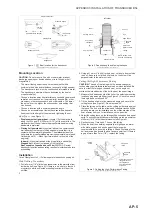
Page 60: ...and to reduce the risk of property damage personal injury and or death WARNING A High Performance Fairing must be installed following the installation instructions that accompany the fairing WARNING Always wear safety goggles a dust mask and ear plugs when installing WARNING The fairing must be installed parallel to the keel to ensure proper boat handling WARNING Do not install a fairing that has ...

Page 61: ...r hole saw cut a hole from outside the hull Be sure to hold the drill plumb so the hole will be perpendicular to the water surface Cutting the High Performance Fairing CAUTION The end of the fairing with the arrows triangular recess always points forward toward the bow when installed Be sure to orient the fairing on the band saw so the angle cut matches the intended side of the hull and not the mi...

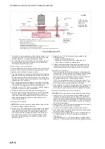
Page 62: ...fairing and seat the transducer firmly within the recess Be sure the arrow on the transducer points toward the triangular recess in the fairing Installing the Transducer 1 From outside the hull thread the transducer cable through the mounting hole Push the stem of the transducer with the fairing in place into the mounting hole using a twisting motion to squeeze out excess sealant see Figure 4 Be s...

Page 63: ...e wrong location drill a second hole in a better location Apply masking tape to the outside of the hull over the incorrect hole and fill it with epoxy 2 Using the appropriate size drill bit or hole saw cut a hole from outside the hull through the outer skin only Be sure to hold the drill plumb so the hole will be perpendicular to the water surface 3 The optimal interior hole diameter is affected b...

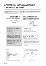
Page 64: ...the bracket for it to release and rotate the transducer upward Mounting on the side of the transom where the propeller blades are moving downward is preferred see Figure 1 Mount the transducer as far away from the propeller as possible while ensuring the transducer s face remains in the water when the boat is turning Record the information found on the cable tag for future reference Part No ______...

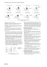
Page 65: ...standard 12 transom angle No shim is needed for this installation If your boat is capable of speeds above 20kn 28MPH install the bracket with one 3 shim taper down This will ensure that the transducer is in contact with the water at high speeds Using shims The bracket is supplied with three shims each one has a 3 angle Up to three shims can be combined for a maximum of 9 The shims are designed to ...

Page 66: ...kHz with the engine off 2 Become familiar with your echosounder s performance at a speed of 4kn 5 MPH 3 Gradually increase the boat speed and observe the gradual decline of performance due to turbulent water flowing under the transducer s face NOTE As the speed increases the performance at 50kHz will deteriorate more rapidly because more acoustic noise is generated at low frequencies 4 If the decl...

Page 67: ...es where they pass through the transom 9 Position the four cable clamps and fasten them in place If used push a cable cover over each cable and screw them in place 10 Route the cables to the instrument being careful not to tear the cable jackets when passing it through the bulkhead s and other parts of the boat Use grommet s to prevent chafing To reduce electrical interference separate the transdu...

Page 68: ...APPENDIX 4 INSTALLATION OF TRANSDUCER TM54 AP 12 This page is intentionally left blank ...

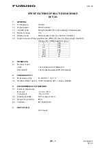
Page 69: ...Pulse length standard Range m PRR times min max 5 600 10 600 40 484 100 200 200 100 500 40 1200 37 2 INTERFACE 2 1 Number of port LAN 1 port Ethernet 10 100Base TX External KP 1 port optional external KP kit required 3 POWER SUPPLY 3 1 Multi beam sonar 12 24 VDC 1 4 0 7 A 3 2 Rectifier PR 62 option 100 110 220 230 VAC 1 phase 50 60Hz 4 ENVIRONMENTAL CONDITIONS 4 1 Ambient temperature Main unit 15 ...

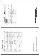
Page 70: ...䢀䢚 ྕᮎᑿ䛾㼇㻖㻖㼉䛿䚸㑅ᢥရ䛾௦ 䡶䡬䢀䢚䜢 䛧䜎䛩䚹 㻯㻻㻰㻱㻌㻺㼁㻹㻮㻱㻾㻌㻱㻺㻰㻵㻺㻳㻌㼃㻵㼀㻴㻌㻎㻖㻖㻎㻌㻵㻺㻰㻵㻯㻭㼀㻱㻿㻌㼀㻴㻱㻌㻯㻻㻰㻱㻌㻺㼁㻹㻮㻱㻾㻌㻻㻲㻌㻾㻱㻼㻾㻱㻿㻱㻺㼀㻭㼀㻵㼂㻱㻌㻹㻭㼀㻱㻾㻵㻭㻸㻚 䠄 ᅗ䛾ᑍἲ䛿䚸ཧ 䛷䛩䚹㻌㻌㻰㻵㻹㻱㻺㻿㻵㻻㻺㻿㻌㻵㻺㻌㻰㻾㻭㼃㻵㻺㻳㻌㻲㻻㻾㻌㻾㻱㻲㻱㻾㻱㻺㻯㻱㻌㻻㻺㻸㼅㻚䠅 5 A 1 2 12 7 3 3 ࠉࠉᅗ 287 1 ྡࠉࠉ 1 0 ᩘ㔞 4 7 㸭ഛ 5 0 5 6 ྕ 12 ᆺྡ㸭つ᱁ 6 5 37 216 167 7 21 0 7 5 6 ᕤ ᮦᩱ 5 㺢㺵㺛㺞㺍㺩㺽㺻㺦㺚㺼ࠉ 㺚㺋 6 7 33 1 6 5 686 2 12 ᅽ Ꮚ 5 03 21 8 9 5 2 12 ᑟ㟁ᛶ㺡㺎㺪㺽 21 8 7 9 7 3 12 00 2 12 㸦 ᅗࡢᑍἲࡣࠊཧ ࡍࠋࠉ 0 16 216 1 5 1 25 5 5 1...

Page 71: ...D 1 20 Sep 2016 H MAKI 20 Sep 2016 H MAKI 20 Sep 2016 H MAKI 20 Sep 2016 H MAKI ...

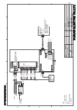
Page 72: ...5 B287B3 75 B287B1 3 7 3 3 1 7 25 02 P P 5 5 ࢧࢿࢵࢺࣁࣈ 7 51 7 8 8 ࡲࡓࡣ 25 08 7 81 7 21 63 ࣝࢳࣇ ࣥࢡࢩࣙࣥࢹ ࢫࣉࣞ 7 7 7 7 7 7 7 7 7 7 0 63 027 21 6 1625 3 9 VT ࣝࢳࣅ ࢯࢼ 08 7 0 621 5 ࢲ 25 ࣁ 5 㺯㺵㺙㺕 33 ࢡࣟ 6 9 7 7 7 1 7 7 7 7 B 20021 7 7 7 1 7 7 3 1 75 16 8 5 7 3 P ȭ 03 6 3 287 3 1 7 0 6 0 17 5 211 7 21 5 0 ᅗ ࣝࢳࣅ ࢯࢼ 08 7 0 621 5 P ȭ ཷἼჾ 75 16 8 5 70 6HS 6HS S 1 13 Sep 2017 H MAKI 13 Sep 2017 H MAKI ...

Page 73: ...display 4 5 side scan display 4 7 Fuse replacement 5 2 G Grid cross section display 4 8 I Installation 1 2 DIP switch settings 3 1 external KP cable 2 5 ground 2 1 LAN cable 2 9 multi beam sonar 1 2 multi function display settings 3 4 operation check 3 3 transducer 1 3 AP 4 AP 8 transducer cable 2 2 wiring 2 1 J JIS cable guide AP 3 L LAN cable installation 2 9 M Maintenance 5 1 Menu tree AP 1 Mul...

Page 74: ...INDEX IN 2 Z Zoom display 4 8 ...

Page 75: ...l Corr 1 2008 title and or number and date of issue of the standard s or other normative document s For assessment see Test Report LIC 12 15 164 LIC 12 15 165 and LIC 12 15 166 February 16 2016 prepared by Labotech International Co Ltd This declaration is issued according to the Directive 2014 30 EU of the European Parliament and of the Council of 26 February 2014 on the harmonisation of the laws ...

Reviews: