background image

21

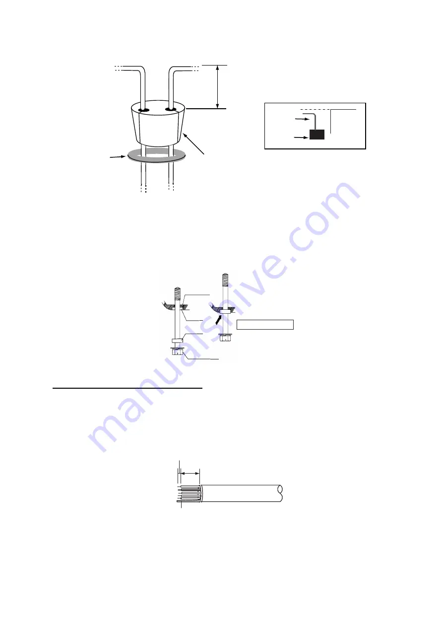
7. Slide the gasket on cables so that the amount of cable above the gasket is lower than the RF 

chassis.

8. Push the gasket and washers into the hole at the bottom of the radar sensor, then fasten four 

pan head screws to fix the plate to the sensor.

9. Release the stay and close the cover.

Note: 

When closing the cover, set the gaskets to grooves in the bottom chassis, then tighten bolts.

Connecting to NMEA2000 equipment

To connect NMEA2000 equipment to the sensor, use an optional NMEA2000 cable, 

M12-05BFFM 

(

φ

6)

 or 

CB-05BFFM (

φ

10)

. Also, the gasket at the bottom of the antenna sensor must be replaced.

1. Do steps 1 to 5 on pages 19 and 20.
2. Fabricate the cable

 M12-05BFFM (

φ

6)

 or 

CB-05BFFM (

φ

10)

 as shown below.

3. Pass the cable through the bottom of the chassis.
4. Insert wires of the cable 

M12-05BFFM (

φ

6)

 or 

CB-05BFFM (

φ

10)

 to the NMEA connector inside 

the radar sensor, consulting the label on the connector for location. As for drain wire, attach 

This height should be lower than the 
RF unit when installed to the bottom 
of the sensor.

Gasket

Washers

RF unit

Gasket

Cable

BOTTOM 
CHASSIS

GASKET

GROO

V

E

HEX BOLT

Tor

q

ue : 9.

8

 ±0.1 

N

  m

.

95

5

Drain wire

Cable M12-05BFFM
or CB-05BFFM

Summary of Contents for DRS12ACM

Page 1: ...OUNTING 1 1 1 Mounting Considerations 1 1 2 Mounting Procedure for DRS2D 4D 2 1 3 Mounting Procedure for DRS4A 6A 12A 25A 3 1 4 Mounting of Power Supply Unit 8 2 WIRING 11 2 1 Wiring inside DRS2D 4D 15 2 2 Wiring inside DRS4A 6A 12A 25A 19 2 3 Wiring of Power Supply Unit 23 SPECIFICATIONS SP 1 PACKING LISTS A 1 OUTLINE DRAWINGS D 1 INTERCONNECTION DIAGRAMS S 1 ...

Page 2: ......

Page 3: ...dous situation which if not avoided canresult in minor or moderate injury Warning Caution Prohibitive Action CAUTION Mandatory Action The radar antenna emits electromagnetic radio frequency RF energy which can be harmful particularly to your eyes Never look directly into the antenna aperture from a close distance while the radar is in operation or expose yourself to the transmitting antenna at a c...

Page 4: ... NO NO PSU 012 NO 12 24 VDC Multi Function Display MFD8 12 TZT9 14 or Multi Function Display BlackBox TZTBB Multi Function Display MFD8 12 TZT9 14 or Multi Function Display BlackBox TZTBB TZT9 TZT14 Power Supply Unit 1 PSU 017 2 Power Supply Unit 1 PSU 017 2 12 24 VDC PSU 012 PSU 012 PSU 012 PSU 012 PSU 012 PSU 012 PSU 012 PSU 012 PSU 012 PSU 012 or PSU 017 PSU 012 or PSU 017 2 The disconnecting d...

Page 5: ...ence to other users the antenna type and its gain should be so chosen that the equivalent isotropically radiated power e i r p is not more than that neces sary for successful communication Importer in Europe The following concern acts as our importer in Europe as defined in DECISION No 768 2008 EC Name FURUNO EUROPE B V Address Ridderhaven 19B 2984 BT Ridderkerk The Netherlands Program No 0359235 ...

Page 6: ...llation Materials CP03 32101 001 025 270 1 set For DRS2D 4D CP03 32601 001 025 780 1 set For DRS4A 6A 12A 25A CP03 32200 000 011 720 1 Two way cable MOD ASW0001 100 10 m for DRS2D 4D 4A 6A 12A CP03 32300 000 011 721 Two way cable MOD ASW0001 150 15 m for DRS2D 4D 4A 6A 12A CP03 32400 000 011 722 Two way cable MOD ASW0001 200 20 m for DRS2D 4D 4A 6A 12A CP03 32500 000 011 723 Two way cable MOD ASW0...

Page 7: ...ith a unit Radome Mount OP03 208 001 078 340 For DRS4D OP03 209 001 078 350 For DRS2D Joint Box TL CAT 012 000 167 140 10 For LAN cable extension LAN Cable MOD Z072 020 000 167 175 10 2 m MOD Z072 050 000 167 176 10 5 m MOD Z072 100 000 167 177 10 10 m Cable Assy M12 05BFFM 010 000 167 965 10 NMEA2000 φ6 w connector 1 m M12 05BFFM 020 000 167 966 10 NMEA2000 φ6 w connector 2 m M12 05BFFM 060 000 1...

Page 8: ...will be affected if the radar sensor is placed too close to it Observe the compass safe distances mentioned in the SAFETY INSTRUCTIONS to prevent interference to a magnetic compass Do not paint the radiator aperture and radome to ensure proper emision of the radar waves When this radar sensor is to be installed on large vessels consider the following points The two way cable run between the radar ...

Page 9: ...orm is 5 mm or less also save the bolts 2 Construct a platform steel or aluminum 6 10 mm in thickness referring to the outline drawing at the back of this manual Fasten the platform to the mounting location Next position the base so the cable entrance is facing the stern Note When drilling holes in the platform be sure they are parallel with the fore and aft line Radar sensor Radar sensor Radar se...

Page 10: ...rawing shows two cable entrance holes one on the radar sensor and one on the rubber mat Use only the one on the rubber mat 1 3 1 Fastening the radiator to the radiator bracket 1 Remove the radiator cap from the radiator bracket 2 Coat the surface of the radiator bracket with silicone sealant as shown in the figure below 3 Coat threaded holes on the antenna radiator with silicone sealant 4 Grease t...

Page 11: ... sensor Use the hex bolts supplied to mount the radar sensor as below 1 Lay the corrosion proof rubber mat supplied on the mounting platform Flat washer Spring washer Hex bolt M8 x 30 Radiator bracket Coat bolts with silicone sealant Antenna radiator O ring Coat threaded holes with silicone sealant Radiator bracket bottom view four Holes where to apply silicone sealant Apply silicone sealant aroun...

Page 12: ...rn 3 Insert four hex bolts M12 x 60 supplied and seal washers φ30 supplied from the top of the housing as shown below STERN BOW Hinge CAUTION Do not lift the radar sensor by the radiator lift it by the housing The radiator may be damaged Hex bolt Seal washer Face projecting part down Flat washer Spring washer Nut ...

Page 13: ...ground terminal on radar sen sor using M6 x 25 bolt nut and flat washer supplied 7 Run the ground wire RW 4747 340 mm supplied between the ground terminal and ground point 8 Coat ground terminal and ground point with silicone sealant as shown below Antenna unit Mounting platform Silicone sealant Flat washer Rubber mat Seal washer Ground wire Hex bolt Flat washer Spring washer Flat washer Hex nut S...

Page 14: ...ove RF unit by unfastening two hex bolts and two fixing bolt For DRS12A 25A unfasten four hex bolts not two fixing bolts to remove the RF unit 5 Lay the corrosion proof rubber mat supplied on the mounting platform 6 Fasten the lower chassis to the mounting platform with hex bolts spring washers flat washers and nuts local supply and then coat flat washers nuts and exposed parts of bolts with sili ...

Page 15: ... 012 013 Name Type Code No Qty Remarks Power supply unit PSU 012 1 PSU 013 For DRS25A Cable assy VL3P VV S2X2C AA050 000 152 217 11 1 5 m LAN cable MOD Z072 050 000 167 176 10 1 5 m standard Self tapping screw 4x20 SUS304 000 158 850 10 4 Fuse FGB0 250V 10A 000 155 839 10 2 For 24 VDC FGB0 250V 15A 000 157 874 10 2 For 12 VDC XH Connector Assembly 03 2345 2P 001 183 760 00 1 For TZT9 14 BB MFD8 MF...

Page 16: ...ad with four self tapping screws 4x20 supplied Location is dry well ventilated Make sufficient maintenance space Installed within 2 5 or 10 m 2 and 10 m optional supply from the multi function display Note When you install the unit on the bulkhead fix the unit with the following direction Self tapping screw 4x20 4 pcs UP ...

Page 17: ...ng When selecting a location keep in mind the following points Fix the power supply unit on the desktop or bulkhead with four tapping screws 4x20 supplied Location is dry well ventilated Make sufficient maintenance space A disconnecting device breaker etc is required when the power cable is connected to ship s mains Name Type Code No Qty Remarks Power supply unit PSU 017 1 Self tapping screw 4x20 ...

Page 18: ...5BFFM φ6 or CB 05BFFM φ10 Note When TZT9 14 BB is connected to the radar sensor confirm that the program ver sion of the radar sensor is 0359235 01 16 or higher Wiring for DRS2D 4D 4A 6A 12A without PSU 012 NOTICE Before connecting or disconnecting the NMEA2000 cable turn off the radar sensor The sensor may become damaged if the power is not turned off RADAR SENSOR DRS4A DRS6A DRS12A NMEA2000 Equi...

Page 19: ...12 12 24 VDC To ship s ground Ground wire Local supply IV 2sq Power Supply Unit PSU 012 Power LAN 3 m supplied with MFD8 12 BB TZT9 14 BB Power cable The input voltage range at the edge of the power cable 10 8 to 31 2 VDC 䋺The power cable is supplied with attached to the unit When connecting the power cable to ship s mains pass through the disconnecting device breaker etc Radar Sensor DRS2D DRS4D ...

Page 20: ...SENSOR DRS25A NMEA2000 Equipment NMEA2000 cable M12 05BFFM ø6 or CB 05BFFM ø10 Ground wire Local supply IV 2sq LAN cable MOD 2072 050 To ship s ground POWER LAN Power Supply Unit PSU 013 Power cable VL3P VV S2X2C AA050 Supplied with PSU 013 To Multi Function Display BlackBox MFDBB TZTBB or Multi Function Display MFD8 12 TZT9 14 ...

Page 21: ... resistor assembly to the cable M12 05BFFM φ6 or CB 05BFFM φ10 and solder them as below 2 Connect wires to the NMEA connector consulting the label on the connector Note This fabrication is not necessary when the external terminators are attached as below Resistor assembly 120 OHM 1007 24 L50 Twisting and soldering White Blue NMEA2000 cable NMEA2000 connector in the sensor Backbone cable External t...

Page 22: ...in the radar sensor and connect the connector of cable power to the power terminal 4 Connect the RJ 45 connector of the cable LAN to the LAN terminal in the radar sensor 5 Push cables of the two way cable into the slits of the gasket inside the radar sensor Note The ends of the gasket are different Larger end should be up Fixing plate for gasket Power terminal Fix the shield cable power with this ...

Page 23: ...screws for the cover Connecting to NMEA2000 equipment To connect NMEA2000 equipment to the sensor wire an optional NMEA2000 cable M12 05BFFM φ6 or CB 05BFFM φ10 as shown below Also the gasket at the bottom of mounting base must be replaced 1 Do steps 1 to 4 on the previous page 2 Refer to the figure below and fabricate the cable M12 05BFFM φ6 or CB 05BFFM φ10 This height should be lower than the R...

Page 24: ...ched inside the radar sensor Use the clamp supplied with the optional gasket Type OP03 203 Code No 001 025 290 15 5 CB 05BFFM cable 370 CB 05BFFM cable 20 65 15 Area fastened with the cable clamp Wind vinyl tape supplied Fabrication of CB 05BFFM cable Fasten the cable tie supplied within 15 mm from the end of vinyl sheath Shield Zoom up Attach the cable clamp using this screw for CB 05BFFM cable F...

Page 25: ... touches the platform near the radar sensor base wind vinyl tape around the cable at the point where is bent 6 Confirm that the rubber gasket is properly positioned and that the triangle mark on the cover is aligned with the triangle mark on the mounting base then tighten the fixing screws for the cover Cable type M12 05BFFM φ6 CB 05BFFM φ10 Gasket Use the gasket supplied in the plastic bag inside...

Page 26: ...nfasten four bolts to detach the plate gasket washer and lid Discard the lid at the bottom of the hole for the gasket 3 Pass the two way cable MOD ASW0001 MOD ASW0002 for DRS25A through the bottom of the chassis and washer 4 Fasten the shield of the power cable of the two way cable part of the foil with the cable clamp in the radar sensor and then connect the power cable to the power terminal as s...

Page 27: ...ch the gasket to the two way cable inserting the cable into the slits on the gasket Fix the power cable at the foil part with this cable clamp Power terminal LAN terminal Power cable LAN cable Black White RF unit Fix the power cable at the copper foil part with this cable clamp Power terminal Gasket LAN terminal White Black LAN cable Blue Red Power cable ...

Page 28: ...NMEA2000 cable M12 05BFFM φ6 or CB 05BFFM φ10 Also the gasket at the bottom of the antenna sensor must be replaced 1 Do steps 1 to 5 on pages 19 and 20 2 Fabricate the cable M12 05BFFM φ6 or CB 05BFFM φ10 as shown below 3 Pass the cable through the bottom of the chassis 4 Insert wires of the cable M12 05BFFM φ6 or CB 05BFFM φ10 to the NMEA connector inside the radar sensor consulting the label on ...

Page 29: ...he RF chassis 8 Do steps 8 and 9 on the previous page Cable type M12 05BFFM φ6 CB 05BFFM φ10 Gasket Use the gasket supplied in the plastic bag inside the radar sensor Use the optional gasket Type OP03 205 Code No 001 025 790 Cable type M12 05BFFM φ6 CB 05BFFM φ10 Gasket Use the gasket supplied in the plastic bag inside the radar sensor Use the optional gasket Type OP03 206 Code No 001 035 290 NMEA...

Page 30: ...propriate connectors in the power supply unit as shown below Note When the power supply unit is connected to TZT9 14 BB attach the XH Connector Asembly supplied with PSU 013 to J7 on the PWR board For details see How to connect TZT9 14 BB supplied with PSU 013 5 Remove two cable clamps shield cover and body cover in that order 6 Connect other cables Body cover Shield cover Pan head screws M3x8 6 p...

Page 31: ...connector in the PSU 012 Note When the power supply unit is connected to TZT9 14 BB attach the XH Connector Assembly supplied with PSU 012 to J7 on the PWR board For details see How to connect TZT9 14 BB supplied with PSU 012 5 Remount the cable clamp shield cover and body cover in that order 6 Connect other cables Body cover Shield cover Pan head screw M3x8 6 pcs Pan head screw M4x12 2 pcs Cable ...

Page 32: ...the disconnecting device breaker etc Replacement of the fuse 1 Remove four self tapping screws 4x20 to dismount the unit 2 Remove four screws M3x8 at the back of the unit to remove the base To ship s mains 12 24 VDC 2 MOD ASW0001 cable To radar sensor DRS2D 4D Power cable 1 2 Be sure to pass through a disconnecting device breaker etc 1 Input voltage range at the edge of the power cable 10 8 to 31 ...

Page 33: ...s indicates high voltage is present 4 Reattach the base and install the unit Note Before fixing the base make sure the waterproofing gasket is correctly seated in the groove in the chassis J1 1 Brown P48V 2 Red DC_N TB1 1 White DC_P 2 Black DC_N LED Fuse F2 1 5A 125V Fuse F1 7A 125V Waterproofing gasket Groove in chassis ...

Page 34: ...i DRS4A 27 5dBi DRS6A 28 5dBi DRS12A 25A 28 5dBi XN12A 30dBi XN13A 1 6 Sidelobe attenuation DRS2D 24 dB within 20 26 dB 20 or more DRS4D 25 dB within 20 27 dB 20 or more DRS4A 20 dB within 20 28 dB 20 or more DRS6A 12A 25A 27 dB within 10 28 dB 10 or more 1 7 Rotation 24 36 48 rpm 2 RADAR FUNCTION 2 1 TX frequency 9410 30 MHz P0N 2 2 Output power nominal DRS2D 2 2 kW DRS4D 4A 4 kW DRS6A 6 kW DRS12...

Page 35: ...upply unit option set unit A 12 24 VDC wind speed 70kt Model DRS2D DRS4D DRS4A DRS6A DRS12A PSU 012 3 8 1 9 A 4 1 2 0 5 0 2 8 6 2 3 0 8 0 3 8 8 5 4 1 7 8 3 7 9 8 4 7 PSU 017 3 6 1 7 A 4 0 1 9 4 ENVIRONMENTAL CONDITION 4 1 Ambient temperature 30 C to 55 C storage 70 C or less 4 2 Relative humidity 95 at 40 C 4 3 Degree of protection Radar sensor IP26 Power supply unit PSU 012 013 IPX0 PSU 017 IP25 ...

Page 36: ...22 4 241 7 6 37 6 5 6 5 A 1 1 01 6 2 2 ޓޓ 176 0 ฬ ޓޓ 0 ᢙ 3 6 ㅜ㧛 4 4 5 ภ 01 ဳฬ㧛ⷙᩰ 5 4 26 105 056 6 10 6 4 5 Ꮏ ᢱ 45 㩆㨺㩣㩦㨹㩆㨶㨺 5 9 5 4 41 5 1 01 㒐ⲁࠧࡓ 14415 10 2411 47 4 6 41 5 1 01 㩁㨶㨹㩖㩩 01 2 1 01 㩍㨼㩄㨽 ຠ 4 5 5614 55 1 1 01 㩔㩨㩒ᐳ 524 0 9 5 4 575 1 01 㩚㩀㩨㩁㩙㩣ᐔᐳ 6 9 5 4 575 1 01 ⷺ㩏㨹㩎 㩆㨷 10 076 575 1 01 ⷺ㩘㩨㩣㩎 ో㩒㩆㩨 10 5 4 9 575 1 01 ⷺ㩏㨹㩎 㩆㨷 10 076 575 1 01 㩔㩨㩒ᐳ 524 0 9 5 4 575 1 01 㧔 ߩኸᴺߪ ޔ ෳ ୯ߢߔ ޓޕ 05 105 0...

Page 37: ...2 0 2 1 6 722 4 241 7 6 37 6 5 6 5 A 3 1 01 6 2 ޓޓ 176 0 ฬ ޓޓ 0 ᢙ 3 6 ㅜ㧛 4 4 5 ภ 01 ဳฬ㧛ⷙᩰ 5 4 26 105 056 6 10 6 4 5 Ꮏ ᢱ 4 4 5 0514 45 45 㩃㨺㩖㩨㩣 ຠ 55 1 59 ㆬᛯ ޓ 61 5 6 1 01 㩃㨺㩖㩨㩣 ຠ 55 1 59 ㆬᛯ ޓ 61 5 6 1 01 㩃㨺㩖㩨㩣 ຠ 55 1 59 ㆬᛯ ޓ 61 5 6 1 01 㩃㨺㩖㩨㩣 ຠ 55 1 59 ㆬᛯ ޓ 61 5 6 1 01 㧔 ߩኸᴺߪ ޔ ෳ ୯ߢߔ ޓޕ 05 105 0 4 9 0 14 4 4 0 10 㧕 㧲㨁㧾㨁㧺㧻 ޓ 㧱㧸㧱㧯㨀㧾㧵㧯 ޓ 㧯㧻 ޓ 㧚㧘㧸㨀㧰 ᮡḰߪ 㨙ߢ ࠆ߇ᔅⷐߦࠃࠅㆬᛯน 56 0 4 0 6 5 16 4 0 6 5 4 51 8 ဳᑼ 㩄...

Page 38: ...01 㩃㨺㩖㩨㩣 ຠ 55 1 59 ㆬᛯ ޓ 61 5 6 1 01 㩃㨺㩖㩨㩣 ຠ 55 1 59 ㆬᛯ ޓ 61 5 6 1 01 㩃 㩖㩨㩣 ຠ 55 1 59 ㆬᛯ ޓ 61 5 6 1 01 㧔 ߩኸᴺߪ ޔ ෳ ୯ߢߔ ޓޕ 05 105 0 4 9 0 14 4 4 0 10 㧕 㧲㨁㧾㨁㧺㧻 ޓ 㧱㧸㧱㧯㨀㧾㧵㧯 ޓ 㧯㧻 ޓ 㧚㧘㧸㨀㧰 ဳᑼ 㩄㨺㩎㩨 ภ߇㧞Ბߩ႐ว ޔ ਅᲑࠃࠅ Ბߦઍࠊࠆㆊᷰᦼຠߢ ࠅ ޔ߅ߥޓޕߔ ߡߞ ߇߆ࠄߜߤޔ ຠ ߪᄌࠊࠅ ߖࠎ ޕ 691 6 2 5 0 1 5 56 14 0 6 6 19 4 241 7 6 5 22 0 2 1 6 722 4 241 7 6 37 6 5 6 5 A 5 ...

Page 39: ...21 Aug 09 R Esumi D 1 ...

Page 40: ...22 Mar 08 R Esumi D 2 ...

Page 41: ...D 3 24 Sep 2015 H MAKI ...

Page 42: ...2 Apr 08 R Esumi D 4 ...

Page 43: ...28 Apr 08 R Esumi D 5 ...

Page 44: ...16 Oct 2012 Y NISHIYAMA D 6 ...

Page 45: ...ND RJ45 MJ A3SPF SHIELD 3 3 MOD ASW0001 10 15 20 30m φ6 1 2 4 5 6 3 7 8 1 2 3 MJ A3SPF 3 MFD8 12 MFDBB MPU 001 MFD8 12 MFDBB MPU 001 マルチファンクションディスプレイ MOD WPAS0001 3m MOD WPAS0001 3m 2 2 RJ45 3 12 24VDC MOD Z072 2 5 10m φ6 CROSS OR RJ45 3 MULTI FUNCTION DISPLAY DRS2D 4D HUB 101 H MAKI MOD Z072 MOD WPAS0001 RJ45 RJ45 24VDC 3 5m マルチファンクションディスプレイTZT9 14接続の場合 CONNECTION TO MULTI FUNCTION DISPLAY TZT9 1...

Page 46: ...RJ45 RJ45 10 15 20 30m MOD ASW0001 φ6 1 2 4 5 6 3 7 8 1 2 3 MJ A3SPF 3 MFD8 12 MFDBB MPU 001 1 2 4 5 6 3 7 8 RJ45 3 MFD8 12 MFDBB MPU 001 マルチファンクションディスプレイ 1 2 3 MJ A3SPF 3 MOD WPAS0001 3m MOD WPAS0001 3m 2 2 MOD Z072 2 5 10m φ6 CROSS OR RJ45 3 RJ45 3 PSU 012 RSB 118 OR IV 2sq 1 2 48V H 48V C クロ BLK シロ WHT TB101 φ7 POWER 1 2 3 48V H 48V L SHIELD MJ A3SPF 3 J11 1 J1 2 3 RTR 092A 093A HUB 101 PSU 012...

Page 47: ...TION DISPLAY MFDBB MPU 001 MFD8 12 マルチファンクションディスプレイ 1 2 3 MJ A3SPF 3 MFDBB MPU 001 ONLY 12 24VDC PSU 012を使わない場合 MFDBBのみ WHEN PSU 012 IS NOT USED FOR MFDBB ONLY 2 1 2 4 5 6 3 7 8 NC NC NC NC 3 P P P P RJ45 J2 PSU 012 2 MOD Z072 2 5 10m φ6 12 24VDC VVRx2C 1 DRAWN CHECKED APPROVED DWG No TITLE NAME 名 称 INTERCONNECTION DIAGRAM 相互結線図 REF No SCALE MASS kg レーダーセンサー RADAR SENSOR T YAMASAKI DRS12A 航法装置またはセ...

Page 48: ...1 SHIPYARD SUPPLY 2 OPTION 注記 1 造船所手配 2 オプション 3 コネクタは工場にて取付済み 3 CONNECTOR PLUG FITTED AT FACTORY RW 4747 0 3m 1 2 3 TXHV NC J305 GND アオ BLU 48V GND 1 2 J4 3 GND 1 IV 2sq 1 2 48V H 48V C クロ BLK シロ WHT TB101 POWER 1 2 4 5 6 3 7 8 NC NC 3 P P P P RJ45 P P P P 1 2 4 5 6 3 7 8 RJ45 3 1 2 4 5 6 3 7 8 J2 1 2 J3 12 24VDC VVRx2C 1 1 J1 シロ WHT VL3P VVS2x2C 5m 12 24VDC クロ BLK 2 3 HUB 101 ETHERNET HUB 2 JUNCT...

Page 49: ...icient Otherwise the invoice with serial number name and stamp of the dealer and date of purchase is shown For the Onboard Warranty your FURUNO certified dealer will take care of all registrations 5 Warranty Claims For the Standard Warranty simply send the defective product together with the invoice to a FURUNO national distributor For the Onboard Warranty contact a FURUNO national distributor or ...

Page 50: ...c or its authorized dealer at the time of request for warranty service This warranty is valid for installation of products manufactured by Furuno Electric Co hereafter FURUNO Any purchases from brick and mortar or web based resellers that are imported into other countries by anyone other than a FURUNO certified dealer agent or subsidiary may not comply with local standards FURUNO strongly recommen...

Page 51: ......

Page 52: ...rinted in Japan Elemental Chlorine Free The paper used in this manual is elemental chlorine free 9 52 Ashihara cho Nishinomiya 662 8580 JAPAN All rights reserved Pub No IME 35670 F3 ETMI DRS2D 4D 4A 25A A JAN 2008 F3 SEP 16 2016 00016745115 ...

Reviews: