background image

3.  BERTHING DISPLAY

3-14

This page is intentionally left blank.

Summary of Contents for DS-60

Page 1: ...DOPPLER SONAR DS 60 OPERATOR S MANUAL www furuno co jp MODEL ...

Page 2: ... Distributor Dealer 9 52 Ashihara cho Nishinomiya 662 8580 JAPAN Telephone 81 0 798 65 2111 Fax 81 0 798 65 4200 A MAR 2010 Printed in Japan All rights reserved A2 JUN 23 2010 Pub No OME 72640 A2 00017233410 00017233410 TOMA DS 60 00017233410 00017233410 0 0 0 1 7 2 3 3 4 1 0 ...

Page 3: ...e holders How to discard this product Discard this product according to local regulations for the disposal of industrial waste For disposal in the USA see the homepage of the Electronics Industries Alliance http www eiae org for the correct method of disposal How to discard a used battery Some FURUNO products have a battery ies To see if your product has a battery ies see the chapter on Maintenanc...

Page 4: ...t if the power remains on Turn off the power at the switchboard if the equipment is emitting smoke or fire Fire or electrical shock can result if the power remains on Do not disassemble or modify the equipment Fire electrical shock or bodily injury can result WARNING Do not put liquid filled containers on or near the equipment Fire or electrical shock can result if a liquid spills into the equipme...

Page 5: ...me the point of reference will be wrong and the gyro indication in error When the rate gyro goes off power outage etc make sure the ship is stationary or traveling in a straight line before turning on the rate gyro CAUTION If an LCD type display is used handle the display with care The panel is made of glass which if broken can cause injury Do not paint the transducer Paint causes a large drop in ...

Page 6: ... 2 5 2 2 4 Current direction 2 5 2 2 5 Wind angle 2 7 2 2 6 Wind averaging time 2 8 2 2 7 ROT sensor 2 8 2 3 How to Set the Speed Alarm 2 9 3 BERTHING DISPLAY 3 1 3 1 Berthing Display Overview 3 1 3 2 Display Range 3 2 3 2 1 How to select a range 3 2 3 2 2 How to pre set ranges 3 2 3 3 Track 3 3 3 3 1 Types of tracks 3 3 3 3 2 How to select the type of track to display 3 4 3 3 3 How to select the ...

Page 7: ...n 5 8 5 7 System Parameters 5 9 6 MAINTENANCE TROUBLESHOOTING 6 1 6 1 Maintenance 6 1 6 2 Consumable Parts 6 2 6 2 1 Fuse replacement 6 2 6 2 2 Product life 6 2 6 3 Troubleshooting 6 3 6 4 Error Messages 6 4 6 5 Diagnostics 6 5 6 5 1 System test 6 5 6 5 2 Display unit test 6 9 6 5 3 LCD test 6 10 6 6 TX Monitor 6 11 6 7 Echo Monitor 6 12 6 8 How to Restore Initial Settings 6 15 APPENDIX 1 MENU TRE...

Page 8: ...n unless properly operated and maintained Please carefully read and follow the operation and maintenance procedures set forth in this manual Thank you for considering and purchasing FURUNO Features The DS 60 is a high precision Doppler Sonar designed for use on VLCC LNG LPG container ships cargo ships etc The DS 60 measures speeds relative to ground and water in the fore stern and transverse direc...

Page 9: ...n 6652002 02 xx March 2010 DS 610 Starter 6652100 01 xx March 2010 Booter 6652101 02 xx March 2010 Main 6652102 02 xx March 2010 FPGA 6652103 00 xx March 2010 DS 620 Starter 6652200 01 xx March 2010 Booter 6652201 02 xx March 2010 Main 6652202 02 xx March 2010 FPGA1 6652203 00 xx March 2010 FPGA2 6652204 00 xx March 2010 RD 501 RD 502 2651009 01 xx August 2009 ...

Page 10: ...vironmental category Protected from weather DS 600 DS 610 DS 620 DS 640 RD 501 RD 502 DS 340 DS 630 DS 631 Exposed to weather Protected from weather by waterproof container DS 600 in Waterproof Box DS 605 DS 600 DISPLAY UNIT MAIN DISPLAY UNIT RD 501 REMOTE CONTROLLER RD 502 DIMMER CONTROLLER RD 50 20 RD 50 20 IEC 61162 Output x 5 IEC 61162 Input x 3 Distance Run Pulse x 4 Alarm System External KP ...

Page 11: ...shown in bold face for example DISP key Menu related items are in brackets for example Key Beep 1 1 Controls 1 1 1 Display Unit DS 600 No Control Function 1 PWR Turn the power on and off 2 DISP Select a display Close the menu and return to last used display In multiple data displays select a data indication to change its unit of measurement with the UNIT key ENT MENU ESC DAY NT PWR DISP TRKG MODE ...

Page 12: ... audible alarm 7 DAY NT Select the daytime and nighttime displays alternately 8 MENU ESC Open the menu Return control to the menu window without making any changes at the menu options window Select the item to change its unit of measurement in multiple data displays Close the menu when the menu window is active 9 ENT Confirm an operation in menu operation Long push to hide or show nav data and 3 a...

Page 13: ...MODE Main display unit Select the tracking mode ground water or auto for the measurement of ship speed Sub display unit Select the tracking mode to ground tracking or water tracking when the tracking mode at the main display unit is ground tracking No Control Function 1 DAY NT Select the daytime and nighttime displays alternately 2 T S Adjust the screen brilliance T to decrease the brilliance S to...

Page 14: ...heck result the equipment stops Reset the power to try to restore normal operation If you cannot restore normal operation contact a FURUNO agent or dealer for instruction To turn off the power press the PWR key Note The screen refreshes slower in low ambient temperature Sub display unit Main display unit Unit Name DS 600 Serial No XXXX Program No 6652002 xx xx ROM OK RAM OK Unit Name DS 610 Serial...

Page 15: ...0 1 4 How to Select a Display Press the DISP key to select a display In the default arrangement there are four dis plays navigation data berthing head up heading and speed and trip distance and total distance A maximum of seven displays are available in full screen or two way horizontal split screen Section 5 1 shows you to set the displays to meet your requirements When a data is lost hyphens for...

Page 16: ...o use this mode Water Measure and display a speed relative to the watermass The depth from the keel must be at least three meters to use this mode However the accuracy is lower when the clear ance is less than 40 m The reference layer can be set with Track Depth on the System menu See section 5 7 Auto Automatically selects ground tracking mode or water tracking mode according to the depth The wate...

Page 17: ...ect the data for which to change its unit Use the MENU ESC key to reverse the selection order 3 Press the UNIT key to change the unit See the table below for item and available units To quit the unit selection press the DISP or MENU ESC key until the yellow highlight disappears Item Available units Berthing display range meters DIV m DIV nautical miles DIV NM DIV Current tide speed knots kn meters...

Page 18: ...tance indication on the displays that shows the trip distance Press the ENT key until the trip distance indication shows all zeroes Trip distance can also be reset from the menu with Trip DIST RESET Trip distance Trip distance total distance display Navigation data display 56 0 Trip distance ...

Page 19: ...selected menu item appear 2 Press S T to select a menu item then press the ENT key Control is then given to the menu options window Note Hereafter we write Select name of menu item then press the ENT key where you use S T to select an item or option and the ENT key to confirm selec tion Daytime CURRENT T WIND DEPTH TRANSDUCER 56 0 Nighttime CURRENT T WIND DEPTH TRANSDUCER 56 0 Currently selected i...

Page 20: ...ption with 2 Press ENT key Spinner box numeric data 1 Set value with 2 Press ENT key to confirm Spinner box alphanumeric data The input cursor is initially at the far left position 1 Select character with 2 Press ENT key to confirm The input cursor moves to next input point 3 Repeat steps 1 and 2 to complete the name 1 Select option with 2 Press ENT key to check or uncheck box Check box Input curs...

Page 21: ...angle drift angle and cur rent tide direction are indicated with purple brown and blue triangles respectively Trip distance Total distance run Drift angle Depth source depth from transducer GPS measured SOG COG Heading Doppler sonar measured SOG STW COG Position ROT source ROT Current tide speed direction Wind reference speed angle 1 2 3 Wind angle marker purple Drift angle marker brown Direction ...

Page 22: ...e to the transducer and is converted into a downward mea sured depth The depth measured to a flat bottom meets the accuracy denoted in the specifications however the depth to a sloping bottom is not the true depth DRIFT The drift angle The drift angle is shown on the 3 axis speed display with a brown tri angle TRIP DIST Trip distance indication TOTAL DIST Total distance run indication You can rese...

Page 23: ...ss the MENU ESC key to open the menu 2 Select Ship s Time then press the ENT key 3 Select Source then press the ENT key 4 Select Internal or NAV EQUIP then press the ENT key Select Internal to use local time or NAV EQUIP to use UTC time For Internal the Local Time ADJ screen appears go to step 5 For NAV EQUIP go to step 6 5 Use S T to set the time difference between local time and UTC time then pr...

Page 24: ...T key 8 Press the DISP key to close the menu 2 2 2 Time format You can display time in UTC or ship s time local time 1 Press the MENU ESC key to open the menu 2 Select Scale Set Up then press the ENT key 3 Select Mode then press the ENT key 4 Select Time then press the ENT key 5 Select UTC or Ship s Time then press the ENT key 6 Press the DISP key to close the menu ...

Page 25: ...el measured by external equipment EXT DBT Depth Below the Transducer measured by other transducer INT DBT Depth Below the Transducer measured by the transducer of the DS 60 5 Press the DISP key to close the menu 2 2 4 Current direction The direction of tide currents can be shown as flowing from or flowing to The current direction indicator blue triangle marker is inside the 3 axis speed display fo...

Page 26: ...2 NAVIGATION DATA DISPLAY 2 6 5 Press the DISP key to close the menu Flow to example 120 Flow from example 300 56 0 56 0 ...

Page 27: ...the ENT key 4 Select Wind then press the ENT key 5 Select True Theoretical or Relative then press the ENT key True The wind speed and angle minus movement of ship reference to North Theoretical The wind speed and angle minus movement of ship reference to ship s bow Relative The speed and relative direction that the wind appears to blow with ship in motion reference to ship s bow 6 Press the DISP k...

Page 28: ...ess the ENT key 3 Select a value then press the ENT key 4 Press the DISP key to close the menu 2 2 7 ROT sensor Select the ROT sensor as follows 1 Press the MENU ESC key to open the menu 2 Select ROT Sensor then press the ENT key 3 Select a source then press the ENT key Internal Select this item if the optional Rate Of Turn Gyro DS 340 is connected External ROT Receive ROT data from external ROT s...

Page 29: ...e alarm with the ALARM ACK key The message remains on the screen until you deactivate the alarm 1 Press the MENU ESC key to open the menu 2 Select Speed Limit Alarm then press the ENT key 3 Select SET then press the ENT key 4 Press S or T to set the maximum allowable speed then press the ENT key The setting range is 0 05 to 40 kn in 0 5 kn increments 5 Press the DISP key to close the menu To deact...

Page 30: ...2 NAVIGATION DATA DISPLAY 2 10 This page is intentionally left blank ...

Page 31: ...er indicates current position The marker is green for ground tracking and blue for water tracking The marker is scaled according to ship length and width set on the Setting Ship Data menu If the range and dimensions of the ship are as shown below the marker is shown with concentric circles Range x 8 Ships length x 30 or Width x 52 Heading Line Indicates your heading Beam Line Speed Vector Shows pr...

Page 32: ...rthing display has a total of 11 ranges Select the ranges to use following the procedure shown below A minimum of one range must be turned on 1 Press the MENU ESC key to open the menu 2 Select Set Up Scale then press the ENT key 3 Select Range then press the ENT key 4 Select a range then press the ENT key Show X in a check box to select the range or remove the X to deselect the range 5 Press T to ...

Page 33: ...ack is black A new dot is added every two seconds and the reference position and stern tracks of the past five minutes are shown A past track marker is added every 30 seconds The markers are colored light blue for water tracking and light green for ground tracking The last five minutes of past track markers are shown You can select the type of past track to show from the menu See section 3 3 3 for...

Page 34: ...he ground and water tracking speed data The marker is purple hollow and dashed to distinguish it from the own ship marker and the past track markers 3 3 2 How to select the type of track to display 1 Press the MENU ESC key to open the menu 2 Select Ship s Track then press the ENT key 3 Select the type of track to display then press the ENT key Select OFF to hide all tracks 4 Press the DISP key to ...

Page 35: ...ack marker only 4 Press the DISP key to close the menu 3 3 4 How to select the predicted track plot interval Select the interval at which to plot the predicted track as follows 1 Press the MENU ESC key to open the menu 2 Select Plot Time then press the ENT key 3 Select a time then press the ENT key A new marker is plotted at equally time spaced intervals of 1 5 of the plot time selected For exampl...

Page 36: ... elapses using the current course and speed You can adjust the length of the vector line to see estimated position at the end of the pre scribed time interval 1 Press the MENU ESC key to open the menu 2 Select Vector Time then press the ENT key 3 Select a vector time then press the ENT key The longer the time the longer the vector line 4 Press the DISP key to close the menu ...

Page 37: ...ow or show only the 3 axis speed data no NAV data Long push the ENT key to show or hide the data in the sequence shown below The data can also be shown or hidden with Data Display in the Scale Set Up menu NAV data 3 axis speed data 3 axis speed data 3 axis speed data in NAV data window 3 axis speed data and NAV data 3 axis speed data NAV data OFF 3 axis speed data in NAV data Long push ENT Long pu...

Page 38: ...imum of three points All berthing lines within the current display range are automatically shown A berthing line is automatically sent to all powered sub dis play units the moment the line is saved 3 6 1 How to create a berthing line Berthing lines can only be created from the main display unit 1 Press the MENU ESC key to open the menu 2 Select Berthing Line then press the ENT key 3 Select Edit th...

Page 39: ...oint 2 Repeat step 1 to complete the name To move the input cursor use the ENT key to move it right the MENU ESC key to move it left Note If you do not enter a name the message Please enter name appears En ter a name 7 Press the ENT key to go to the SET menu 8 Press T to select the LAT line of Point1 then press the ENT key 9 Use S or T to select the first digit of the latitude position then press ...

Page 40: ...the distance between two consecutive points is more than one degree the message Points too far maximum distance between points is 1 degree ap pears Reenter point s 13 Select Harbour View then press the ENT key The display shows Berthing line Name of berthing line and Latitude and longitude position of each point Name of berthing line Position of points North Up Berthing line ...

Page 41: ...its when the ENT key is pressed Note If you select Harbour View without entering a name the message Har bour Name Berthing Line plans must be named individually please enter name appears Enter a name 15 To make another berthing line repeat steps 4 14 To finish press the DISP key Note You can edit berthing lines Open the Berthing Line menu select Edit then select a berthing line The remaining proce...

Page 42: ...ine is created To send the berthing lines after a sub display unit becomes active do as follows 1 Press the MENU ESC key to open the menu 2 Select Berthing Line then press the ENT key 3 Select Share then press the ENT key 4 Select Yes then press the ENT key All berthing lines in the sub display units are replaced with the berthing lines from the main display unit 5 Press the DISP key to close the ...

Page 43: ...rom both the main and sub display units 1 Press the MENU ESC key to open the menu 2 Select Berthing Line then press the ENT key 3 Select Delete then press the ENT key to show the list of berthing lines 4 Select the line to delete then press the ENT key You are asked if you are sure to delete the line 5 Select Yes then press the ENT key 6 Press the DISP key to close the menu ...

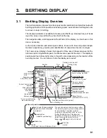
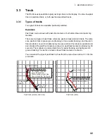
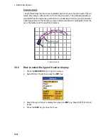
Page 44: ...3 BERTHING DISPLAY 3 14 This page is intentionally left blank ...

Page 45: ...hic display available with the sub display unit provides absolute speed or ahead and astern speeds in a speedometer arrangement 4 1 Speed Graphic Indications Tracking mode SOG or STW Tracking mode Tracking mode monitor Ahead speed Astern speed ...

Page 46: ...ns The total display range for the two indica tions is 70 knots and you can divide that total as required 1 Press the MENU ESC key to open the menu 2 Select Scale Set Up then press the ENT key 3 Select Speed Graphic then press the ENT key 4 Select the display number default display number for the graphic display is DISP5 where to show the speed graphic display then press the ENT key ...

Page 47: ...y 8 Select the scale range for the ahead speed then press the ENT key 9 Press the DISP key to close the menu 4 3 How to Select the Display Format for the Speed Graphic The speed graphic can show absolute speed or ahead and astern speeds Absolute speed is shown in three digits and ahead and astern speeds in four digits 1 Press the MENU ESC key to open the menu 2 Select Speed Select then press the E...

Page 48: ...ing Three digit speed indication Speedometer display 1 axis speed display FWD When Direction SYM is set to Text FWD or AFT is shown FWD or AFT not shown when Arrows is selected When Direction SYM is set to Text FWD or AFT is shown Arrows shown when Arrows is selected No text or arrows shown No text or arrows shown Forward After setting Four digit speed indication Vector setting Three digit speed i...

Page 49: ... Press the MENU ESC key to open the menu 2 Select Scale Set Up then press the ENT key 3 Select SYM Location then press the ENT key 4 Select Left or Right then press the ENT key Left The pointer moves rightward with increase in ahead speed and the zero point for the speedometers is on the left Right The pointer moves leftward with increase in ahead speed and the zero point for the speedometers is o...

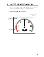
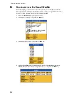
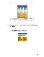
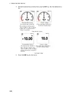
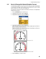
Page 50: ...4 SPEED GRAPHIC DISPLAY 4 6 This page is intentionally left blank ...

Page 51: ...en and two way horizontal split screen A full screen display can show a graphic display navigation data berthing speed graphic sub display unit only or digital data trip distance heading etc A two way horizontal split screen can show two digital data 1 Press the MENU ESC key to open the menu 2 Select Display then press the ENT key 3 Select a display number DISP1 DISP7 then press the ENT key Full s...

Page 52: ...on the next page for the appearance of the displays For the two way horizontal split screen the screen shown below appears after you select the data to show in the top half of the screen Select a data item for the bottom half of the screen then press the ENT key 6 Press the DISP key to close the menu Options available with full screen Options available with two way horizontal split screen Grayed i...

Page 53: ...sub display unit only Heading and 3 axis speed 2 axis speed 1 axis speed sub display unit only Trip distance Total distance 56 0 DPTH EXT Keel 56 0 56 0 Trip distance ROT Total distance heading Trip distance total distance Heading ROT Full screen displays Horizontal split displays TOTAL DIST TOTAL DIST ...

Page 54: ...T key 3 Select ON or OFF then press the ENT key 4 Press the DISP key to close the menu 5 3 How to Adjust Key Dimmer You can adjust the dimmer for the keys as follows 1 Press the MENU ESC key to open the menu 2 Select Key BRILL then press the ENT key 3 Select a dimmer level then press the ENT key The higher the figure the higher the dimmer level 4 Press the DISP key to close the menu ...

Page 55: ...wn with arrows or text 1 Press the MENU ESC key to open the menu 2 Select Scale Set Up then press the ENT key 3 Select Direction SYM then press the ENT key 4 Select Arrows or Text then press the ENT key 5 Press the DISP key to close the menu Arrows Text STBD S PORT P FWD AFT Navigation data display berthing display ...

Page 56: ... the MENU ESC key to open the menu 2 Select Scale Set Up then press the ENT key 3 Select SYM Location then press the ENT key 4 Select Left or Right then press the ENT key Left The direction indicators are on the right side of the speed indications Right The direction indicators are on the left side of the speed indications 5 Press the DISP key to close the menu Direction symbols in heading and spe...

Page 57: ...distance run 1 Press the MENU ESC key to open the menu 2 Select Total DIST then press the ENT key 3 RESET is selected press the ENT key You are asked if you are sure to reset the total distance run 4 Select Yes then press the ENT key 5 Press the DISP key to close the menu ...

Page 58: ...ENU ESC key to open the menu 2 Select Total DIST then press the ENT key 3 Select SET then press the ENT key 4 Use S or T to set a value then press the ENT key You can move the cursor to the right with the ENT key Use the MENU ESC key to move the cursor to the left 5 Repeat step 4 as required 6 Press the DISP key to close the menu ...

Page 59: ...rameters The System Parameters menu provides the functions that once set do not require regular adjustment 1 Press the MENU ESC key to open the menu 2 Select System then press the ENT key 3 Select System Parameters then press the ENT key ...

Page 60: ...ry second No Averaging 10s 30s 60s 90s 120s IR Turn the interference rejector on or off Turn the rejector on when an echosounder is connected to the DS 60 to prevent mutual interference ON OFF Log Pulse Speed Select the data to use to calculate distance run STW GPS SOG STW GPS SOG GPS STW Log Pulse Output Select the log pulse speed to output to external equipment Forward Forward speed only Forward...

Page 61: ...event scratch ing using tissue paper and an LCD cleaner To remove dirt or salt deposits use an LCD cleaner wiping slowly with tissue paper so as to dissolve the dirt or salt Change paper frequently so the salt or dirt will not scratch the LCD Do not use commercial cleaners to clean any part of the equipment Com mercial cleaners can remove paint and markings Transducer Marine life and growth on the...

Page 62: ... Use the correct fuse 6 2 2 Product life Unit Fuse Rating Type Code No Qty Remarks Display Unit 2A FGMB 2A AC125V PBF 000 157 479 10 1 Inside unit Transceiver Unit 3A FGB01 3A AC250V PBF 000 155 841 10 2 Inside unit Distributor Unit 5A FGB01 5A AC250V PBF 000 155 840 10 2 Inside unit Rate of turn Gyro 2A FGB01 2A AC250V PBF 000 155 829 10 1 Inside unit Unit Lifespan Hrs Replacement Part DS 600 Bac...

Page 63: ...ase the brilliance Doppler speed indication The indication does not change display has frozen and the speed unit is red Air bubbles on the transducer face The ground tracking mode is used when the depth is 200 m or more Wait for the air bubbles to disappear Select the water tracking mode or auto mode The indication shows Air bubbles on the transducer face The ground tracking mode is in use when th...

Page 64: ...me the most important error message is displayed See the table below for error message and priority Error category Unit error Error code POWER FAIL 100 SYSTEM FAIL DS 620 B voltage circuit 210 B voltage 211 5V voltage 212 12 voltage 213 DS 340 Temperature high 220 Optical line 221 PI control 222 DS 610 Communication with DS 600 231 Communication with DS 620 232 SPEED ALARM Speed alarm 300 ECHO FAI...

Page 65: ... TEST 4 Press the ENT key The results of the display unit test appear Description of test results for the Display Unit DS 600 The results of the ROM and RAM check are shown as OK normal or NG No Good For any NG reset the power and try the test again If the NG condition continues contact your dealer for instruction SENSOR shows the results of the connection test with DS 610 OK for nor mal no indica...

Page 66: ...keys The key s on screen rectangle fills in red if the key is normal Press the key again and the red fill is removed 5 Press the DISP key to test the Distributor Unit DS 610 Description of test results for the Distributor Unit DS 610 The results of the ROM RAM and EEPROM check are shown as OK or NG For any NG reset the power and try the test again If the NG condition contin ues contact your dealer...

Page 67: ... instruction DS 610 shows the results of the connection test with the DS 610 OK for normal or no indication for error B Volt 5V and 12V show the voltage of the related circuits The program number of the starter program booter program main program FPGA1 program and FPGA2 program are shown 7 To quit the self test press the MENU ESC key three times OK OK 122 4 5 0 12 2 XXXX STARTER PROG No 6652200 xx...

Page 68: ...ours the LCD has been powered up to a max imum of 999 999 hours BRILL shows the current LCD brilliance setting Press S T to check the bril liance control circuit Check if the indication and brilliance level agree 5V shows the voltage of the 5V circuit The program number of the starter program booter program main program re mote program and dimmer program are shown The program no indication is blan...

Page 69: ...ENT key 4 Press any key except the MENU ESC key to display each color in the order shown in the figure below To test the brilliance control circuit press S T 5 Control is returned to the menu after the blue gradation is shown Press the DISP key to close the menu 1 Start 2 Black 3 White 4 Red 6 Blue 7 Black gradation 8 Red gradation 9 Green gradation 10 Blue gradation 5 Green Other Keys Next MENU E...

Page 70: ...onitor feature to see the TX condition by amplitude and cycle of waveform 1 Press the MENU ESC key to open the menu 2 Select TX Monitor then press the ENT key 3 Start is selected press the ENT key to show the TX monitor display 4 To quit the TX monitor press the MENU ESC key 100V ...

Page 71: ...n press the ENT key 3 Select 3 Way Split or 12 Way Split 3 Way Split Select beams 1 3 and or channels 1 9 to monitor You can select any three to monitor 12 Way Split Monitor all beams 1 3 and all channels 1 9 4 Press the ENT key One of the following displays appears depending on the se lection you made at step 3 For 12 Way Split go to step 5 To clear the echo data press the DISP key For 3 Way Spli...

Page 72: ...t1 then press the ENT key 2 Select the beam or channel to display then press the ENT key 3 Select the beam or channel for Point2 and Point3 in the same method 4 After you selected the beams or channels to show for Point3 the following screen appears ...

Page 73: ...To clear the echo data press the DISP key 7 The Setting menu controls the gain TX mode and exit from the echo monitor At the echo monitor display press the MENU ESC key to show the Setting menu 1 You can change the gain to see the echoes under different gain settings Select Gain then press the ENT key 2 Use S or T to set the gain then press the ENT key 3 TX Mode on the Setting menu stops or starts...

Page 74: ... select Exit then press the ENT key 6 8 How to Restore Initial Settings If you feel the equipment is not operating correctly one cause can be abnormal equip ment settings Try restoring initial settings to restore normal operation All initial set tings are restored however trip distance and total distance run are not reset 1 Press the MENU ESC key to open the menu 2 Select User RESET then press the...

Page 75: ...M RESET Speed Limit Alarm 1 SET 40 0kn 0 00 40 00 kn OFF Berthing Line 1 Edit Share Delete Wind Average No Averaging 1min 2min 3min 5min 10min Key Beep ON OFF Key BRILL 1 2 3 4 5 6 7 8 Speed Select 2 Forward After Vector Echo Monitor 1 3 Way Split 12 Way Split TX Monitor 1 Start ROT Sensor 1 Internal External ROT External HDG TESTS System TEST Display Unit TEST LCD TEST Continued on next page DISP...

Page 76: ...TW GPS SOG STW GPS SOG GPS STW Log Pulse Output Forward Forward After Vector Analog Speed STW GPS SOG STW GPS SOG GPS STW Analog Output Forward Forward After Vector Beam Direction Forward After TVG Curve 0 19 0 Trim 12 5 deg 12 5 deg Heel 12 5 deg 12 5 deg XDCR 60 0 deg 60 0 deg Compass Calibration 12 5 deg 12 5 deg SOG Calibration 12 5 12 5 STW Calibration 12 5 12 5 LOA 50 0m 400 0m B 5 0m 100 0m...

Page 77: ...ps IEC 61162 1 2 Output Same as above Baud rate fixed at 38400 bps for DS 600 Data bits 8 D7 0 Parity none Stop bits 1 Data sentences Input Data format is IEC 61162 1 Edition 3 unless noted otherwise DBT Depth below transducer DPT Depth D0 D1 D2 D3 D4 D5 D6 D7 Start bit Stop bit Data bits 1 2 Water depth feet 3 4 Water depth m 5 6 Water depth fathom DBT x x f x x M x x F hh CR LF 1 2 3 4 5 6 DPT x...

Page 78: ...use GLL llll ll a yyyyy yyy a hhmmss ss x x hh CR LF 1 Latitude 2 N S 3 Longitude 4 E W 5 UTC of Position 6 Status A Data valid V Data not valid 7 Mode indicator A Autonomous D Differential mode S Simulator mode 1 2 3 4 5 6 7 GNS hhmmss ss llll ll a yyyyy yyy a cc xx x x x x x x x x x x hh CR LF 1 2 3 4 5 6 7 8 9 10 11 12 1 UTC of position no use 2 Latitude 3 N S 4 Longitude 5 E W 6 Mode indicator...

Page 79: ...2 3 4 5 1 Wind angle degrees 2 Reference R relative T true 3 Wind speed 4 Wind speed units K M N 5 Status A data valid V data invalid RMC hhmmss ss A llll ll a yyyyy yy a x x x x xxxxxx x x a a hh CR LF 1 2 3 4 5 6 7 8 9 10 1112 1 UTC of position fix no use 2 Status A data valid V navigation receiver warning 3 Latitude 4 N S 5 Longitude 6 E W 7 Speed over ground knots 8 Course over ground degrees ...

Page 80: ...xx xxxx xx xx hh CR LF 1 2 3 4 5 6 1 UTC 2 Day 01 to 31 UTC 3 Month 01 to 12 UTC 4 Year UTC 5 Local zone hours 00 to 13 6 Local zone minutes 00 to 59 VBW x x x x A x x x x A x x A x x A hh CR LF 1 2 3 4 5 6 7 8 9 10 1 Longitudinal water speed knots 2 Transverse water speed knots 3 Status water speed A data valid V data invalid 4 Longitudinal ground speed knots 5 Transverse ground speed knots 6 Sta...

Page 81: ...c 4 Magnetic 5 Current speed knots 6 N VHW x x T x x M x x N x x K hh CR LF 1 2 3 4 5 6 7 8 1 Heading degrees true 2 T 3 Heading degrees magnetic no use 4 no use 5 Speed knots 6 N 7 Speed km h 8 K VLW x x N x x N x x N x x N hh CR LF 1 2 3 4 5 6 7 8 1 Total cumulative water distance nautical miles 2 Nautical miles 3 Water distance since reset 4 Nautical miles 5 Total cumulative ground distance no ...

Page 82: ... and 38400 bps The serial interface complies with IEC 61162 2 Input port RD A RD B Output port TD A TD B LTC1535C RD A GND Isolated RS485 Transceiver Logical High A B 0 2V Logical Low A B 0 2V RD B LTC1535C TD A GND Isolated RS485 Transceiver Logical High A B 0 2V Logical Low A B 0 2V TD B ...

Page 83: ...e Over The Ground CUR Current DBK Depth Below Keel DBT Depth Below Transducer DEL Delete DISP Display DIST Distance DPTH Depth DRIFT Drift Angle E East ENT Enter ESC Escape EXT External FAIL Fail FWD Forward GAIN Gain GPS Global Positioning System H UP Head Up HDG Heading IR Interference Rejector INT Internal I O Input Output L Length LAT Latitude LCD Liquid Crystal Display L L Latitude Longitude ...

Page 84: ...Select SIM Simulation SOG Speed Over The Ground SPD Speed STBD Starboard STW Speed Through The Water SYM Symbol T True Trim Trim UTC Coordinated Universal Time Trip Trip TRK Track TVG Time Variable Gain TX Transmit VECT Vector WPT Waypoint W West XDCR Transducer Abbreviation Meaning deg or degree s fm fathom s ft feet foot hrs hours km kilometer s kn knot s m meter s min or minute s NM nautical mi...

Page 85: ... MCN BOARD 02P6345 LCD NL6448BC26 22F 000 171 704 10 DISTRIBUTOR UNIT DS 610 MAIN BOARD 66P3950 001 090 660 I F BOARD 66P3951 001 090 650 CONT BOARD 66P3952 001 090 630 ZNR BOARD 66P3953 001 090 610 TRANSCEIVER UNIT DS 620 MAIN BOARD 66P3960 001 097 930 TX BOARD 66P3961 001 090 720 PWR BOARD 66P3962 001 090 690 FIL BOARD 66P3964 001 090 700 JUNCTION BOX DS 640 JTB BOARD 66P3970 001 090 800 REMOTE ...

Page 86: ...S LIST PARTS LOCATION AP 12 Parts Location Display Unit DS 600 Display Unit DS 600 front panel assembly Display Unit DS 600 rear panel assembly PNL BOARD 26P0007 MCN BOARD 02P6345 LCD NL6448BC26 22F MAIN BOARD 26P0006 ...

Page 87: ...APPENDIX 4 PARTS LIST PARTS LOCATION AP 13 Distributor Unit DS 610 Distributor Unit DS 610 CONT BOARD 66P3952 MAIN BOARD 66P3950 I F BOARD 66P3951 ZNR BOARD 66P3953 Cover removed ...

Page 88: ... LIST PARTS LOCATION AP 14 Transceiver Unit DS 620 Transceiver Unit DS 620 Transceiver Unit DS 620 MAIN BOARD 66P3960 removed MAIN BOARD 66P3960 TX BOARD 66P3961 FIL BOARD 66P3964 inside this housing PWR BOARD 66P3962 ...

Page 89: ...APPENDIX 4 PARTS LIST PARTS LOCATION AP 15 Junction Box DS 640 Junction Box DS 640 Remote Controller RD 501 Dimmer Controller RD 502 Remote Controller RD 501 JTB BOARD 66P3970 RMT BOARD 26P0012 ...

Page 90: ...hever is greater 1 7 Current direction speed 0 0 to 9 9 kn 360 clearance required 10 m or more Working depth is influenced by conditions of installation and sea water Water tracking accuracy may lower at the sea bed depth 40 m or less 2 DISPLAY UNIT 2 1 Main display unit LCD 640 x 480 dot VGA 2 2 Brilliance 0 2 to 500 cd m2 2 3 View angle Up down left right 75 or more color is not considered 2 4 D...

Page 91: ...ENTAL CONDITION 5 1 Ambient temperature Main display unit 25 C to 55 C Others 15 C to 55 C 5 2 Relative humidity 93 at 40 C 5 3 Degree of protection Main display unit IP56 front panel Remote display IP22 Transceiver unit Junction box IP44 Distributor IP22 5 4 Vibration IEC 60945 6 COATING COLOR N2 5 ...

Page 92: ...ller 1 3 1 5 1 7 Display arrangement 5 1 Display unit controls 1 1 Display unit test 6 9 E Echo monitor 6 12 ENT key 1 2 1 8 Error message 6 4 F Fuse replacment 6 2 H Heading averaging 5 10 I Initial settings restore 6 15 Input sentences AP 3 Interference rejector 5 10 K Key beep 5 4 Key dimmer 5 4 L LCD test 6 10 Log pulse output 5 10 Log pulse speed source 5 10 M Maintenance 6 1 Menu operation 1...

Page 93: ... resetting 5 7 setting 5 8 Track past track 3 3 past track format 3 5 predicted track 3 4 predicted track plot interval 3 5 type to display 3 4 Tracking depth 5 10 Tracking mode 1 6 Tracking mode monitor 1 6 Trip distance 1 8 TRKG MODE key 1 2 1 6 Troubleshooting 6 3 TVG curve 5 10 Tx monitor 6 11 U UNIT key main display unit 1 2 1 7 remote controller 1 3 1 7 Units 1 7 W Wind angle 2 7 Wind averag...

Page 94: ......

Reviews: