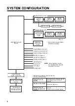
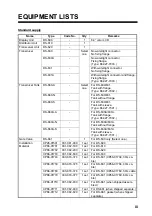
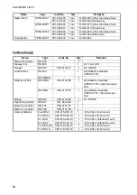
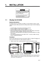
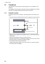
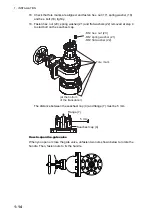
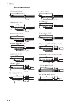
1. INSTALLATION
1-12
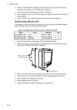
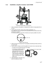
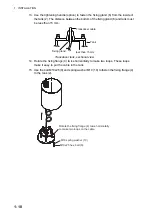
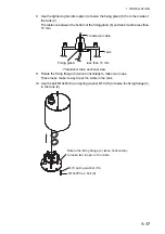
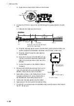
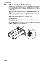
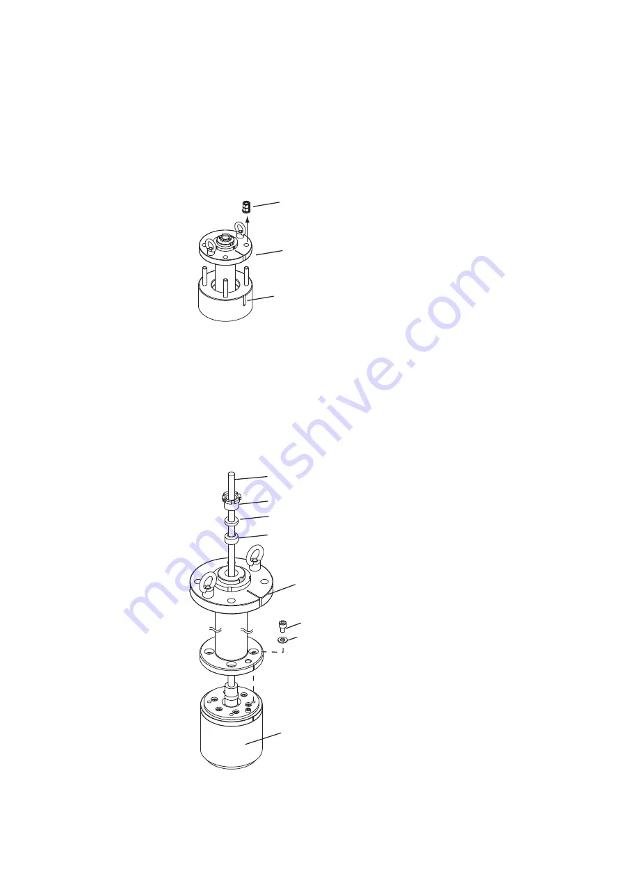
2. Set the spacer (3) to the place selected at paragraph 1.4.1.
The “FORE-AFT” line on the spacer must be parallel with the ship's fore and aft
line (within 3°). For horizontal direction, the bottom of the spacer must be parallel
with the ship's draft.
3. Weld the spacer (3) to the ship's hull. The welding and doubling methods are left
up to the shipyard.
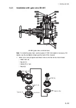
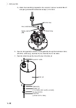
4. Unfasten M12 hex. nut (20), spring washer (21) and flat washer (22) to remove
the shaft (6) from the seachest cap (4).
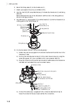
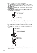
5. Paint the gate valve (2), spacer (3) and seachest cap (4) the same color as ship's
body. Paint only gray-colored areas; for other part, seal with a masking tape.
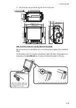
6. Pass the cable from the transducer (1) through the shaft (6) from the bottom.
7. Apply liquid gasket (supplied) on the top of the transducer (1).
8. Use hex. bolt (26) and seal washer (27) to fasten the transducer (1) to the shaft
(6).
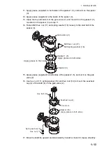
9. Pass the gasket (8), flat washer (7) and fixing gland (11) through the transducer
cable.
10. Fasten the fixing gland (11) to the top of the shaft (6).
The height between the top of the fixing gland (11) and the top of the shaft (6) must
be less than 7 mm.
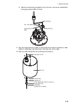
-M12 hex. nut (20)
-M12 spring washer (21)
-M12 flat washer (22)
Seachest cap (4)
Shaft (6)
Gasket (8)
Washer (7)
The hollow side must be downward.
Fixing gland (11)
Seal washer (27)
Hex. bolt (26)
Transducer (1)
Shaft (6)
Transducer cable
Summary of Contents for DS-60
Page 51: ...APPENDIX 1 CALIBRATION AP 3 ...
Page 59: ...8 Mar 2010 Y NISHIYAMA D 1 ...
Page 60: ...18 Dec 2012 Y NISHIYAMA D 2 ...
Page 61: ...18 Dec 2012 Y NISHIYAMA D 3 ...
Page 62: ...D 4 30 Jun 2015 H MAKI ...
Page 63: ...D 5 30 Jun 2015 H MAKI ...
Page 64: ...1 Jul 2011 Y NISHIYAMA D 6 ...
Page 65: ...29 Mar 2011 Y NISHIYAMA D 7 ...
Page 66: ...29 Mar 2011 Y NISHIYAMA D 8 ...
Page 67: ...D 9 30 Jun 2015 H MAKI ...
Page 68: ...D 10 30 Jun 2015 H MAKI ...
Page 69: ...D 11 15 Apr 2016 H MAKI ...
Page 70: ...D 12 15 Apr 2016 H MAKI ...
Page 71: ...D 13 15 Apr 2016 H MAKI ...
Page 72: ...D 14 15 May 2015 H MAKI ...


