background image

NETWORK SOUNDER

ETR-6/10N

Summary of Contents for ETR-10N

Page 1: ...NETWORK SOUNDER ETR 6 10N ...

Page 2: ...c h o N i s h i n o m i ya J a p a n Tele p h o n e 0 7 9 8 6 5 2 111 Tele f a x 0 7 9 8 6 5 4 2 0 0 Your L ocal Age nt D eal er All rights reserved PUB No OME 20240 ET R 6 1 0 N MIMA FIRS T EDITION MA R 2001 Printed in Japan ...

Page 3: ...ble for the proper installation of the equipment FURUNO will assume no responsibility for any damage associated with improper installation Be sure that the power supply is compatible with the voltage rating of the equipment Connection of an incorrect power supply can cause fire or equipment damage The voltage rating of the equipment appears on the label above the power connector ELECTRICAL SHOCK H...

Page 4: ... of chloro phrene or polychloride vinyl which is easily by damaged plastic solvents such as toulene Locate the cable well away from plastic solvents Use the correct fuse Use of a wrong fuse can cause fire or equipment damage Standard compass Steering compass Network Sounder 0 80 m 0 55 m A warning label is attached to the equip ment Do not remove the label If the label is missing or illegible cont...

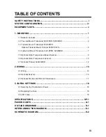
Page 5: ... Mount Transducer 520 5PSD 520 5MSD 7 1 5 Optional Water Temperature Speed Sensors 9 1 6 Optional Water Temperature Sensors 10 1 7 Optional Triducer 524ST MSD 12 2 WIRING 13 2 1 Wiring 13 2 2 Optional Sensors 15 2 3 Optional 50 kHz and 200 kHz Transducers 17 3 INITIAL SETTINGS 18 3 1 Selecting the Transmission Power 18 3 2 Replacing the Fuse 19 3 3 LED Lamp 19 SPECIFICATIONS SP 1 PACKING LISTS A 1...

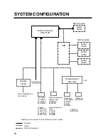
Page 6: ...62M 50B 9B 50B 92M Transducer 200B 5 5S Rectifier PR 62 100 110 220 230 VAC 1φ 50 60 Hz 50 200 1T 50 200 12M Distribution Box MB 1000 Standard Option External Equipment Water temperature speed sensor ST 02MSB ST 02PSB Water temperature sensor T 02MTB T 02MSB T 03MSB 1 kW Radar Plotter Radar Plotter Radar Plotter HUB HUB may be connected to 3 sets of NAVnet radar or plotter NAVnet series NAVnet ser...

Page 7: ...Code No Qty Remarks 1 Network Sounder ETR 6 10N 1 2 Spare Parts SP02 04301 1 set CP02 06800 000 027 897 MJ A3SPF0013 035 3 A MJ A6SPF0014 050 5 m Tapping screw 3 Installation Materials CP02 06810 000 027 898 1 set MJ A3SPF0013 035 3 A Tapping screw ...

Page 8: ...26 520 5PSD 000 015 204 520 5PWD 000 015 126 520 5MSD 000 015 127 50B 6 000 015 042 10 m For 1 kW 000 015 043 15 m For 1 kW 000 015 018 30 m For 1 kW 50B 6B 000 015 255 40 m For 1 kW 50B 6G 000 015 016 10 m 50B 9B 000 015 065 15 m For 1 kW 50B 62M 000 015 251 For 1 kW 50B 92M 000 015 252 For 1 kW 200B 5 000 015 027 10 m For 1 kW 200B 5S 000 015 029 10 m For 1 kW 50 200 1T 000 015 170 10 m For 1 kW...

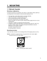
Page 9: ...magnetic field generating equipment such as motors and generators Leave slack in cables for maintenance and servicing ease A magnetic compass will be affected if the network sounder placed too close to the magnetic compass Observe the following compass safe distances to prevent disturbance to the magnetic compass a Standard compass 0 80 meters b Steering compass 0 55 meters Mounting procedure Fast...

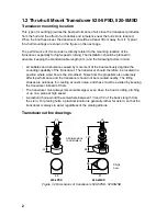
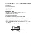
Page 10: ...eriously degrade the sounding capability of the transducer The transducer should therefore be located in a position where water flow is the smoothest Noise from the propellers also adversely affects performance and the transducer should not be mounted nearby The lifting strakes are notorious for creating acoustic noise and these must be avoided by keeping the transducer inboard of them The transdu...

Page 11: ...ucer mounting location on deep V hull High speed V planing hull Within the wetted bottom area Deadrise angle within 15 Figure 1 4 Transducer mounting location on high speed V planing hull Typical thru hull mount transducer installations Flat washer Rubber washer Hull bottom Hull bottom Deep V Hull Flat Hull Fairing block Figure 1 5 Typical thru hull mount transducer installations ...

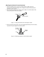
Page 12: ...e for stuffing tube Upper half Lower half Saw along slope of hull Figure 1 6 Construction of fairing block 3 Drill a hole just large enough to pass the threaded stuffing tube of the transducer through the hull making sure it is drilled vertically 4 Apply a sufficient amount of high quality caulking compound to the top surface of the transducer around the threads of the stuffing tube and inside the...

Page 13: ...t transducer flush with hull for flat hulls A suitable mounting location is at least 50 cm away from the engine and where the water flow is smooth 1 Drill four pilot holes in the mounting location 2 Attach the transducer to the bracket with tapping screws supplied 3 Adjust the transducer position so the transducer faces right to the seabed Note If necessary to improve water flow and minimize air b...

Page 14: ... care must be taken not to damage the transducer when the boat is hauled out of the water and put on the trailer No 2 M5x14 M5x20 M5x20 Figure 1 9 Transom mount transducer projecting from hull Transducer preparation Before putting the boat in water wipe the face of the transducer thoroughly with a detergent liquid soap This will lessen the time necessary for the transducer to have good contact wit...

Page 15: ...ting location should be where the hull is of single hull thickness and is void of air or flotation materials other than solid fiberglass between the transducer face and the water Do not place the transducer over hull struts or ribs which run under the hull Avoid a location where the rising angle of the hull exceeds 15 to minimize the effect of the boat s rolling You will finalize the mounting loca...

Page 16: ...alant to 40 C before usage to soften it Coat the transducer face and mounting location with silicone sealant Transducer face Silicone sealant Figure 1 11 Coating the transducer face with silicone sealant 3 Press the transducer firmly down on the hull and gently twist it back and forth to remove any air which may be trapped in the silicone sealant Hull Silicone sealant Squeeze out air bubbles Figur...

Page 17: ...in hole to allow for circulation of cooling water Select a place free from vibration 1 Dry dock the boat 2 Make a hole of approx 51 mm in diameter 3 Unfasten locknut and remove the sensor section 4 Apply high grade sealant to the flange of the sensor 5 Pass the sensor casing through the hole 6 Face the notch on the sensor toward boat s bow and tighten the flange 7 Set the sensor section to the sen...

Page 18: ...cation with cable clamp When the cable is led in through the transom board make a hole of approx 17 mm in diameter to pass the connector After passing the cable fill the hole with a sealing compound M5x20 Mount sensor flush with hull bottom D D 50cm Figure 1 14 How to install transom mount water temperature sensor T 02MTB ...

Page 19: ... T 02MSB T 03MSB Mounting procedure 1 Drill a hole of 21 mm in diameter in the mounting location 2 Pass the sensor cable through the hole 3 Pass gasket washer and locknut onto cable in that order 4 Coat the sensor flange with high quality sealant and then fasten the sensor with the locknut Torque max 59N m 5 Launch the boat to check for water leakage around the sensor Mounting procedure 1 Drill a ...

Page 20: ...mance and the transducer should not be mounted nearby The lifting strakes are notorious for creating acoustic noise and these must be avoided by keeping the transducer inboard of them The transducer must always remain submerged even when the boat is rolling pitching or up on a plane at high speed A practical choice would be somewhere between 1 3 and 1 2 of the boat s length from the stern For plan...

Page 21: ...ound terminal White Black Shield Figure 2 1 Network sounder Power cable Connect the power cable to the power connector Connect the leads to the battery 12 24 VDC white to plus terminal and black to minus terminal Cable connector Power cable w fuse 3A Lead wire White Black BATTERY Shield Figure 2 2 Connecting the power cable to the battery ...

Page 22: ...ce to the picture Shorten the ground wire as much as possible For FRP vessels install a ground plate that measures about 20 cm by 30 cm on the outside of the hull bottom to provide a ground point Ground the equipment to prevent mutual interference CAUTION Note Use a closed lug to make the ground connection at the network sounder Do not use an open type lug ...

Page 23: ...8 9 10 MJ A10SPF SPD TEMP TEMP0V SHIELD V NC NC XDR XDR SHIELD XDR XDR port on the ETR 6 10N Temperature sensor Transducer Figure 2 3 Connection of water temperature speed sensor Connection of water temperature speed sensor MJ A6SRMD SHIELD TEMP TEMP0V SPD0V SPD V NC 1 2 3 4 5 6 MJ A10SRMD NC NC NC NC NC NC NC XDR XDR SHIELD XDR 1 2 3 4 5 6 7 8 9 10 4 7 3 1 2 5 6 8 9 10 MJ A10SPF TEMP TEMP0V SPD0V...

Page 24: ...rproof connector Bind tape end with cable tie MJ A6SRMD MJ A10SRMD MJ A10SPF Connect to XDR port at network sounder Water temp water temp speed sensor connector Transducer connector Figure 2 5 Connection of transducer water temperature sensor water temperature speed sensor ...

Page 25: ...0kHz 200kHz SHIELD RED RED BLK BLK TB2 1 2 3 4 5 J2 J1 BLK 3 2 1 WHT TB1 02P6168 Jumper block setting J2 Full power output J1 Reduced output SHIELD RED BLU GRN BLK TB2 1 2 3 4 5 1 2 3 TB1 50 200 1T or 50 200 12M SHIELD BLK WHT Figure 2 6 Distributor MB 1000 Distribution Box Type MB 1000 Code No 000 040 809 Name Type Code No Qty Remarks Distribution Box MB 1000 000 040 805 1 Cable w 8P connector su...

Page 26: ...tall the 1 kW transducer change the jumper connector to 3 4 from 1 2 on J12 as follows 1 Detach the power cable from the connector 2 Open the cover of the ETR 6 10N 3 Remove the jumper connector on J12 by using long nose pliers 4 Insert it to 3 4 pins of the J12 for 1 kW transducer Note Do not insert the jumper connector upside down 5 Close the cover Figure 3 1 Location of parts inside ETR 6 10N J...

Page 27: ...tact a FURUNO agent or dealer for advice CAUTION Use the correct fuse Use of a wrong fuse can cause fire or equipment damage 3 3 LED Lamp The green LED lamp on the front panel lights or flashes according to equipment stats When a radar or plotter is OFF or the network sounder is not connected to a radar or plotter the LED lamp flashes for 3 minutes and then lights continuously When a radar or plot...

Page 28: ...ier 1 4 Network protocol Ethernet 10BASE T 1 5 Depth Range and Pulse Repetition Rate Range m PRR min 2 1500 5 1500 10 750 40 375 100 150 200 75 400 41 1200 12 2 POWER SUPPLY 2 1 Main Unit 12 24 VDC 1 0 0 5 A 12 0 VA max at 1 kW output Stand by 1 0 VA or less 3 ENVIRONMENTAL CONDITION 3 1 Ambient Temperature 15 C to 55 C 3 2 Relative Humidity 95 at 40 C 3 3 Water proofing IPX2 3 4 Vibration IEC 609...

Page 29: ......

Page 30: ......

Page 31: ......

Page 32: ......

Page 33: ......

Reviews: