U
lstein Power & Control AS
This document and its content is the property of ULSTEIN. Non-
public information contained herein shall be treated as
Confidential Information. No use, copying, citation or publication
of this document or its content is permitted without prior written
consent from ULSTEIN. Any conflicts arising from unauthorized
use shall be governed by the laws of Norway.
File Name:
BRI-D32004-01II (D)
System Installation
Manual.doc
Page:
Page 32 of
56
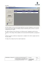
3.4.11.
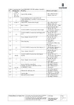
Network port configuration
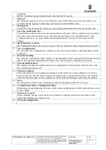
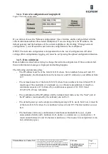
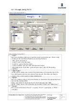
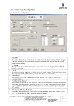
Figure 19: Network port configuration
1
"On/Off"
As for the other ports, you can choose to enable or disable the network port. By leaving this
checkbox unchecked, no network port will be activated and all other parameters on this
screen will be ignored.
2
"Protocol"
Here you can choose what kind of protocol you want to use for the port, between UDP,
Multicast and TCP.
3
"Type"
Here you can choose what type of port it will be, between Reader, Writer and Server. Note
that, if you chose the UDP protocol, you can not choose the Server type.
4
"Broadcast"
Only usable if you chose UDP Reader or UDP Writer. Check it if you want to use a
broadcast address.
5
"Set Dest from Header"
Only usable if you chose Reader or Server. Checking it will disable and ignore the field 10.
If checked, incoming NMEA sentences having a TCP header containing the field d:A/ias
(e.g. "\d:GPS2,c:16857 4.31 *A3") will then be rerouted to the port having the alias Alias
(here GPS2).
6
"Convert to Ethernet-Protocol"
If checked, all outputs will be prefixed by an Ethernet header of the form \s:Aiias,c:16857
4.31 *A3, containing the Alias of the port and a timestamp
Summary of Contents for FA-150
Page 2: ...This page left intentionally blank ...
Page 4: ...This page left intentionally blank ...
Page 5: ...Revision history manual Rev A B C Description Date dd mm yyyy Sign A A 06 05 2015 HAB ...
Page 6: ...This page left intentionally blank ...
Page 8: ...This page left intentionally blank ...
Page 9: ...Index divider Section 1 N ...
Page 10: ......
Page 12: ...PRINTED IN JAPAN UAIS TRANSPONDER FA 150 ...
Page 53: ...Antenna Cable Set CP20 02700 004 381 160 CP20 02710 004 381 170 A 8 ...
Page 54: ...Antenna cable Set CP24 00300 000 041 938 CP24 00310 000 041 939 A 9 ...
Page 55: ...Y Hatai D 1 ...
Page 56: ...Y Hatai D 2 ...
Page 57: ...Y Hatai D 3 ...
Page 58: ...Y Hatai D 4 ...
Page 59: ...Feb 19 03 D 5 ...
Page 60: ...May 20 03 D 6 ...
Page 61: ...Feb 22 05 D 7 ...
Page 62: ...Jan 9 03 D 8 ...
Page 63: ...Mar 11 04 H Hayashi D 9 ...
Page 64: ...Feb 02 05 D 10 ...
Page 65: ...Nov 28 03 D 11 ...
Page 66: ...Oct 02 03 D 12 ...
Page 67: ...H Hayashi Mar 10 05 D 13 ...
Page 69: ...Index divider Section 2 N ...
Page 70: ......
Page 72: ...This page left intentionally blank ...
Page 129: ...Index divider Section 3 N ...
Page 130: ......
Page 187: ...Index divider Section 4 N ...
Page 188: ......
Page 190: ...TECHNICAL MANUAL A100K11209 v 1 3 Sound Reception System VSS V2 Installation User Manual ...
Page 204: ...15 VSS V2 Technical Manual A100K11209 v 1 3 4 7 Cable Connection Diagram ...
Page 206: ...17 VSS V2 Technical Manual A100K11209 v 1 3 5 2 VSS V2 Master Panel Dimensions in mm ...
Page 207: ...18 A100K11209 v 1 3 VSS V2 Technical Manual 5 3 VSS V2 Slave Panel Dimensions in mm ...

