U
lstein Power & Control AS
This document and its content is the property of ULSTEIN. Non-
public information contained herein shall be treated as
Confidential Information. No use, copying, citation or publication
of this document or its content is permitted without prior written
consent from ULSTEIN. Any conflicts arising from unauthorized
use shall be governed by the laws of Norway.
File Name:
BRI-D32004-01II (D)
System Installation
Manual.doc
Page:
Page 36 of
56
4.1.4.
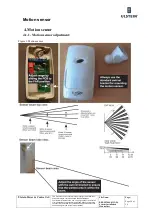
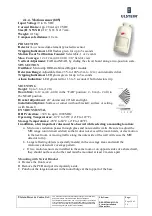
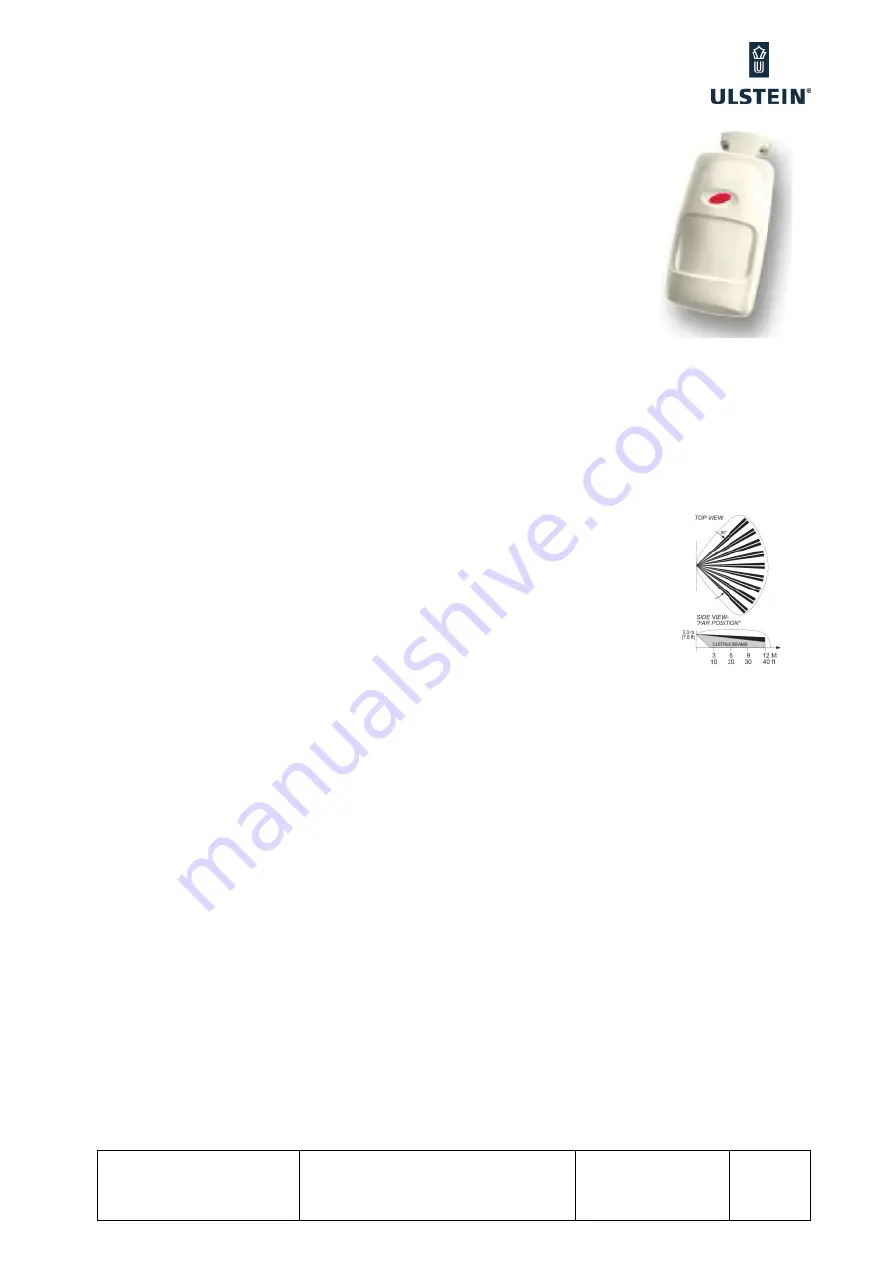
Motion sensor (805)
Input Voltage:
9 to 16 VDC
Current Drain:
App. 28 mA@ 12 VDC
Size (H X W X D):
117 X 65 X 217 mm.
Weight:
0,15 kg
Compass safe distance:
10 em.
PIR SECTION
Detector:
Low noise dual-element pyroelectric sensor
Tripping Indication:
LED flashes green for up to 5 seconds
Motion Event Verification Counter:
Selectable, 1 or 2 events
Max. Coverage:
12 x 12 m (40 x 40 ft) / 90° field of view
Vertical Adjustment:
FAR and NEAR, by sliding the circuit board along a two-position scale.
MW SECTION
Oscillator:
Microstrip DRO-stabilized Doppler module
Detection Range:
Adjustable from 25% to 100% (3 m to 12 m) on internal red dial.
Tripping Indication:
LED glows green for up to 5 seconds
Alarm Indication:
LED glows red for 1.3 to 5 seconds if both detectors trip
MOUNTING
Height
:
Up to 3.6 m (12 ft)
Room Size:
8 -12 m (24 - 40 ft) in the “FAR” position; 2 - 8 m (6 - 24 ft) in
the NEAR position.
Bracket Adjustment
:
20° downward, 20° left and right.
Installation Options
:
Surface or corner (without bracket); surface or ceiling
(with bracket)
ENVIRONMENTAL
RFI Protection:
>30 V/m up to 1000 MHz.
Operating Temperatures:
-10°C to 50°C (14°F to 122°F).
Storage Temperatures:
-20°C to 60°C (-4°F to 140°F).
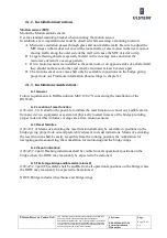
In addition, a few important rules must be observed while selecting a mounting location:
a.
Microwave radiation passes through glass and non-metallic walls. Be sure to adjust the
MW range (on internal red dial) so that it does not exceed the room limits, or else motion
in the next room or moving traffic along the outer side of the wall will cause the MW
detector to trip.
b.
Large reflecting objects (especially metals) in the coverage area can distort the
microwave detector's coverage pattern.
c.
If two motion sensors are installed in the same room or on opposite sides of a shared wall,
they should not face each other and must be mounted at least 2 meters apart.
Mounting with Swivel Bracket
A. Remove the front cover.
B. Remove the PCB and put it temporarily aside.
C. Punch out the large knockout in the round bulge at the top part of the base.
Summary of Contents for FA-150
Page 2: ...This page left intentionally blank ...
Page 4: ...This page left intentionally blank ...
Page 5: ...Revision history manual Rev A B C Description Date dd mm yyyy Sign A A 06 05 2015 HAB ...
Page 6: ...This page left intentionally blank ...
Page 8: ...This page left intentionally blank ...
Page 9: ...Index divider Section 1 N ...
Page 10: ......
Page 12: ...PRINTED IN JAPAN UAIS TRANSPONDER FA 150 ...
Page 53: ...Antenna Cable Set CP20 02700 004 381 160 CP20 02710 004 381 170 A 8 ...
Page 54: ...Antenna cable Set CP24 00300 000 041 938 CP24 00310 000 041 939 A 9 ...
Page 55: ...Y Hatai D 1 ...
Page 56: ...Y Hatai D 2 ...
Page 57: ...Y Hatai D 3 ...
Page 58: ...Y Hatai D 4 ...
Page 59: ...Feb 19 03 D 5 ...
Page 60: ...May 20 03 D 6 ...
Page 61: ...Feb 22 05 D 7 ...
Page 62: ...Jan 9 03 D 8 ...
Page 63: ...Mar 11 04 H Hayashi D 9 ...
Page 64: ...Feb 02 05 D 10 ...
Page 65: ...Nov 28 03 D 11 ...
Page 66: ...Oct 02 03 D 12 ...
Page 67: ...H Hayashi Mar 10 05 D 13 ...
Page 69: ...Index divider Section 2 N ...
Page 70: ......
Page 72: ...This page left intentionally blank ...
Page 129: ...Index divider Section 3 N ...
Page 130: ......
Page 187: ...Index divider Section 4 N ...
Page 188: ......
Page 190: ...TECHNICAL MANUAL A100K11209 v 1 3 Sound Reception System VSS V2 Installation User Manual ...
Page 204: ...15 VSS V2 Technical Manual A100K11209 v 1 3 4 7 Cable Connection Diagram ...
Page 206: ...17 VSS V2 Technical Manual A100K11209 v 1 3 5 2 VSS V2 Master Panel Dimensions in mm ...
Page 207: ...18 A100K11209 v 1 3 VSS V2 Technical Manual 5 3 VSS V2 Slave Panel Dimensions in mm ...


