U
lstein Power & Control AS
This document and its content is the property of ULSTEIN. Non-
public information contained herein shall be treated as
Confidential Information. No use, copying, citation or publication
of this document or its content is permitted without prior written
consent from ULSTEIN. Any conflicts arising from unauthorized
use shall be governed by the laws of Norway.
File Name:
BRI-D32004-01II (D)
System Installation
Manual.doc
Page:
Page 9 of 56
2.2.3.
Ergonomics
1
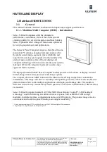
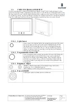
Adjust the unit height so that the top of the screen is at or below eye level. Your eyes
should look slightly downwards when viewing the middle of the screen.
2
The brightness of displays is limited. Sunlight passing directly through the bridge
windows - or its reflection – which falls upon the screen workplaces must be reduced by
suitable means (negatively inclined window surfaces, venetian blinds, distance from the
windows, dark colouring of the deckhead). However, units can be offered with optical
enhanced technology to reduce reflections and are viewable in direct sun light, but as a
general rule the units at the bridge wing area is recommended to be installed or mounted
by suitable alignment or bulkhead / deckhead mounting in such a way that reflections of
light from the front pane of the display are not directed into the observer’s viewing
direction.
3
The use of ordinary commercial filter plates or filter films is not permitted for items of
equipment that require approval (by optical effects, “aids” of that kind can suppress
small radar targets, for example).
2.2.4.
General installation
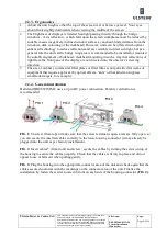
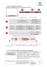
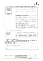
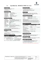
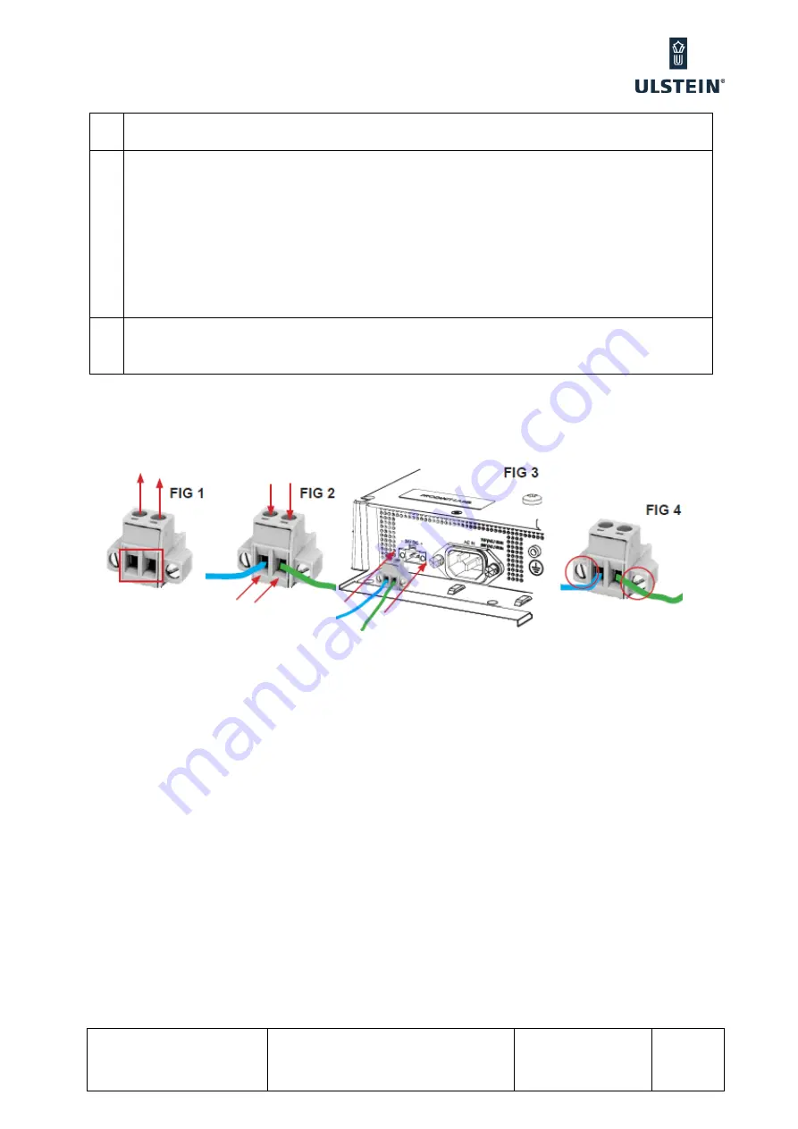
Hatteland HD08T21MMC uses a 2-pin DC power connection. Polarity verification is
recommended
FIG 1:
Unscrew (from top) or make sure that the screw terminal (square area) are fully open, so
you can secure the inserted cables correctly to the loose housing connector (it may already be
plugged into the unit as per factory installation).
FIG 2:
Insert cables* (from front) and screw / secure the cables by turning the screw on top of
the housing to secure the cables properly. Check that the cables is firmly in place and do not
appear loose or falls out when pulling gently.
FIG 3:
Plug the housing into the appropriate connector area of the unit and check again that the
cables secured conforms with the markings on the connector area of the unit. Finalize the
installation by fasten the screws located in front on each side of the housing connector
(FIG 4).
Summary of Contents for FA-150
Page 2: ...This page left intentionally blank ...
Page 4: ...This page left intentionally blank ...
Page 5: ...Revision history manual Rev A B C Description Date dd mm yyyy Sign A A 06 05 2015 HAB ...
Page 6: ...This page left intentionally blank ...
Page 8: ...This page left intentionally blank ...
Page 9: ...Index divider Section 1 N ...
Page 10: ......
Page 12: ...PRINTED IN JAPAN UAIS TRANSPONDER FA 150 ...
Page 53: ...Antenna Cable Set CP20 02700 004 381 160 CP20 02710 004 381 170 A 8 ...
Page 54: ...Antenna cable Set CP24 00300 000 041 938 CP24 00310 000 041 939 A 9 ...
Page 55: ...Y Hatai D 1 ...
Page 56: ...Y Hatai D 2 ...
Page 57: ...Y Hatai D 3 ...
Page 58: ...Y Hatai D 4 ...
Page 59: ...Feb 19 03 D 5 ...
Page 60: ...May 20 03 D 6 ...
Page 61: ...Feb 22 05 D 7 ...
Page 62: ...Jan 9 03 D 8 ...
Page 63: ...Mar 11 04 H Hayashi D 9 ...
Page 64: ...Feb 02 05 D 10 ...
Page 65: ...Nov 28 03 D 11 ...
Page 66: ...Oct 02 03 D 12 ...
Page 67: ...H Hayashi Mar 10 05 D 13 ...
Page 69: ...Index divider Section 2 N ...
Page 70: ......
Page 72: ...This page left intentionally blank ...
Page 129: ...Index divider Section 3 N ...
Page 130: ......
Page 187: ...Index divider Section 4 N ...
Page 188: ......
Page 190: ...TECHNICAL MANUAL A100K11209 v 1 3 Sound Reception System VSS V2 Installation User Manual ...
Page 204: ...15 VSS V2 Technical Manual A100K11209 v 1 3 4 7 Cable Connection Diagram ...
Page 206: ...17 VSS V2 Technical Manual A100K11209 v 1 3 5 2 VSS V2 Master Panel Dimensions in mm ...
Page 207: ...18 A100K11209 v 1 3 VSS V2 Technical Manual 5 3 VSS V2 Slave Panel Dimensions in mm ...

