2
A100K11209 v.1.3
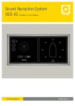
VSS-V2 Technical Manual
About this Document
Document Scope
This document describes system features, models, interfaces and
functions for the VSS-V2 Sound Reception System. It also includes
instructions for installation, commissioning and adjustment, and
provides the end-user with the necessary information to operate the
VSS-V2 system.
Product Information
Item number
Type number
Description
1021001100
VSS-MP
VSS Master Panel - V2
1021001200
VSS-SP
VSS Slave Panel - V2
1021002100
VSS-MU
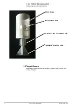
VSS Microphone Unit - V2
Publication Log
Rev. Date
Author
Comments
1.0
12.8.2012
SEN
Published
1.1
12.11.2012
SEN
Small updates PA mute, mounting of mic. unit
1.2
30.10.2013
SEN
Important text for installation of microphone unit
added, p.11. Updated text system function p.5.
Updated cable connection diagram p.15.
Corr. number of LEDs p.20,23.
1.3
08.01.2014
SEN
Environment temprature for VSS-MU changed
from
-30
o
C
to +55
o
C to -55
o
C
to +55
o
C
Related Documentation
For further information, refer to the following documentation:
Doc. number Documentation
A100K11278
Autocad drawing VSS - V2 Master Panel
A100K11279
Autocad drawing VSS - V2 Slave Panel
A100K11277
Autocad drawing VSS - V2 Microphone Unit
A100K11050
VSS - V2 System datasheet
Abbreviations
The list below should define all abbreviations used in this document:
Abbreviation
Actual meaning
DSP
Digital Signal Processor
UTP
Upper Threshold Point
Summary of Contents for FA-150
Page 2: ...This page left intentionally blank ...
Page 4: ...This page left intentionally blank ...
Page 5: ...Revision history manual Rev A B C Description Date dd mm yyyy Sign A A 06 05 2015 HAB ...
Page 6: ...This page left intentionally blank ...
Page 8: ...This page left intentionally blank ...
Page 9: ...Index divider Section 1 N ...
Page 10: ......
Page 12: ...PRINTED IN JAPAN UAIS TRANSPONDER FA 150 ...
Page 53: ...Antenna Cable Set CP20 02700 004 381 160 CP20 02710 004 381 170 A 8 ...
Page 54: ...Antenna cable Set CP24 00300 000 041 938 CP24 00310 000 041 939 A 9 ...
Page 55: ...Y Hatai D 1 ...
Page 56: ...Y Hatai D 2 ...
Page 57: ...Y Hatai D 3 ...
Page 58: ...Y Hatai D 4 ...
Page 59: ...Feb 19 03 D 5 ...
Page 60: ...May 20 03 D 6 ...
Page 61: ...Feb 22 05 D 7 ...
Page 62: ...Jan 9 03 D 8 ...
Page 63: ...Mar 11 04 H Hayashi D 9 ...
Page 64: ...Feb 02 05 D 10 ...
Page 65: ...Nov 28 03 D 11 ...
Page 66: ...Oct 02 03 D 12 ...
Page 67: ...H Hayashi Mar 10 05 D 13 ...
Page 69: ...Index divider Section 2 N ...
Page 70: ......
Page 72: ...This page left intentionally blank ...
Page 129: ...Index divider Section 3 N ...
Page 130: ......
Page 187: ...Index divider Section 4 N ...
Page 188: ......
Page 190: ...TECHNICAL MANUAL A100K11209 v 1 3 Sound Reception System VSS V2 Installation User Manual ...
Page 204: ...15 VSS V2 Technical Manual A100K11209 v 1 3 4 7 Cable Connection Diagram ...
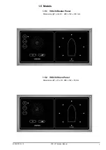
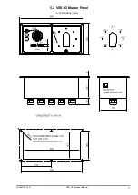
Page 206: ...17 VSS V2 Technical Manual A100K11209 v 1 3 5 2 VSS V2 Master Panel Dimensions in mm ...
Page 207: ...18 A100K11209 v 1 3 VSS V2 Technical Manual 5 3 VSS V2 Slave Panel Dimensions in mm ...

