5
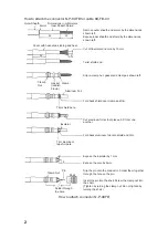
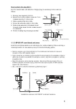
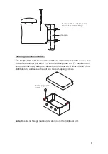
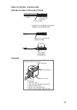
How to attach the plug M-P-7
Lay the coaxial cable and attach an M-type plug (if necessary) to the cable as
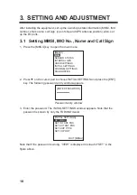
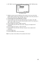
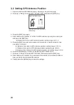
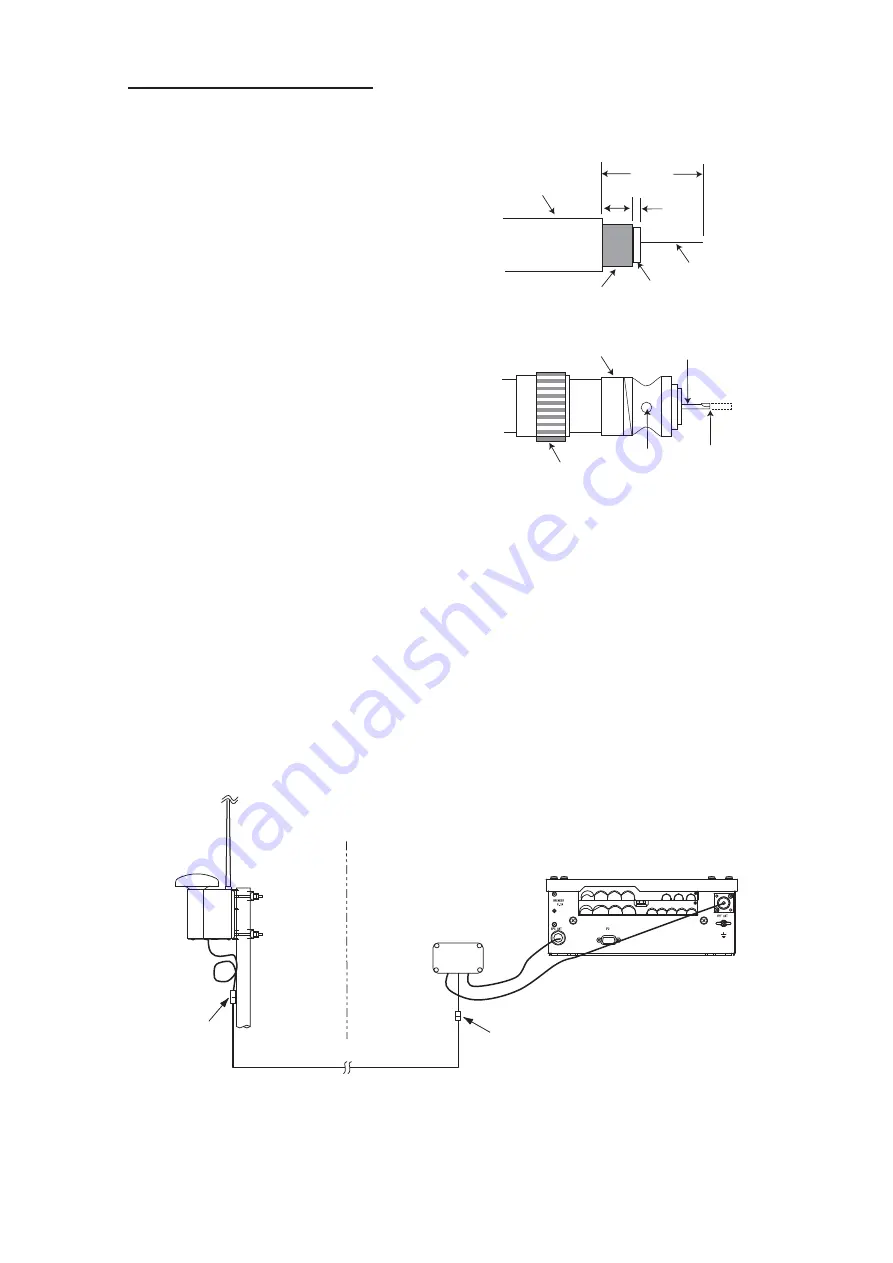
follows.
1. Remove the sheath by 30 mm.
2. Bare 23 mm of the center conductor. Trim
braided shield by 5 mm and tin.
3. Slide coupling ring onto cable.
4. Screw the plug assembly on the cable.
5. Solder plug assembly to braided shield
through solder holes. Solder contact sleeve
to conductor.
6. Screw coupling ring into plug assembly.
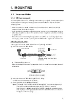
1.1.3 GPS/VHF combined antenna
Install the combined antenna unit referring to the outline drawing. When selecting a
mounting location for the antenna, keep in mind the following points.
•
Select a location out of the radar beam. The radar beam will obstruct or prevent
reception of the GPS satellite signal.
•
There should be no interfering object within the line-of-sight to the satellites. Objects
within line-of-sight to a satellite, for example, a mast, may block reception or prolong
acquisition time.
•
Mount the antenna unit as high as possible. Mounting it this way keeps it free of
interfering objects and water spray, which can interrupt reception of GPS satellite
signal if the water freezes.
•
Also, refer to the antenna installation guidelines page 3.
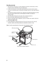
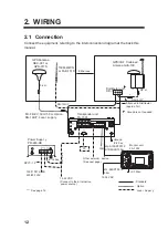
Outdoor
Indoor
N-P-8 DF B
N-P-8 DF B
Distributor DB-1
GPS
UAIS Transponder
VHF
RG-10U/Y
Installation overview of GPS/VHF combined antenna
Sheath
30 mm
5 mm
2 mm
Conductor
Insulator
Braided shield
Plug assembly
Contact sleeve
Cut conductor here.
Solder both
sides of hole.
Coupling ring
Summary of Contents for FA-150
Page 2: ...This page left intentionally blank ...
Page 4: ...This page left intentionally blank ...
Page 5: ...Revision history manual Rev A B C Description Date dd mm yyyy Sign A A 06 05 2015 HAB ...
Page 6: ...This page left intentionally blank ...
Page 8: ...This page left intentionally blank ...
Page 9: ...Index divider Section 1 N ...
Page 10: ......
Page 12: ...PRINTED IN JAPAN UAIS TRANSPONDER FA 150 ...
Page 53: ...Antenna Cable Set CP20 02700 004 381 160 CP20 02710 004 381 170 A 8 ...
Page 54: ...Antenna cable Set CP24 00300 000 041 938 CP24 00310 000 041 939 A 9 ...
Page 55: ...Y Hatai D 1 ...
Page 56: ...Y Hatai D 2 ...
Page 57: ...Y Hatai D 3 ...
Page 58: ...Y Hatai D 4 ...
Page 59: ...Feb 19 03 D 5 ...
Page 60: ...May 20 03 D 6 ...
Page 61: ...Feb 22 05 D 7 ...
Page 62: ...Jan 9 03 D 8 ...
Page 63: ...Mar 11 04 H Hayashi D 9 ...
Page 64: ...Feb 02 05 D 10 ...
Page 65: ...Nov 28 03 D 11 ...
Page 66: ...Oct 02 03 D 12 ...
Page 67: ...H Hayashi Mar 10 05 D 13 ...
Page 69: ...Index divider Section 2 N ...
Page 70: ......
Page 72: ...This page left intentionally blank ...
Page 129: ...Index divider Section 3 N ...
Page 130: ......
Page 187: ...Index divider Section 4 N ...
Page 188: ......
Page 190: ...TECHNICAL MANUAL A100K11209 v 1 3 Sound Reception System VSS V2 Installation User Manual ...
Page 204: ...15 VSS V2 Technical Manual A100K11209 v 1 3 4 7 Cable Connection Diagram ...
Page 206: ...17 VSS V2 Technical Manual A100K11209 v 1 3 5 2 VSS V2 Master Panel Dimensions in mm ...
Page 207: ...18 A100K11209 v 1 3 VSS V2 Technical Manual 5 3 VSS V2 Slave Panel Dimensions in mm ...


