12
2. WIRING
2.1 Connection
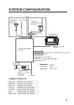
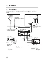
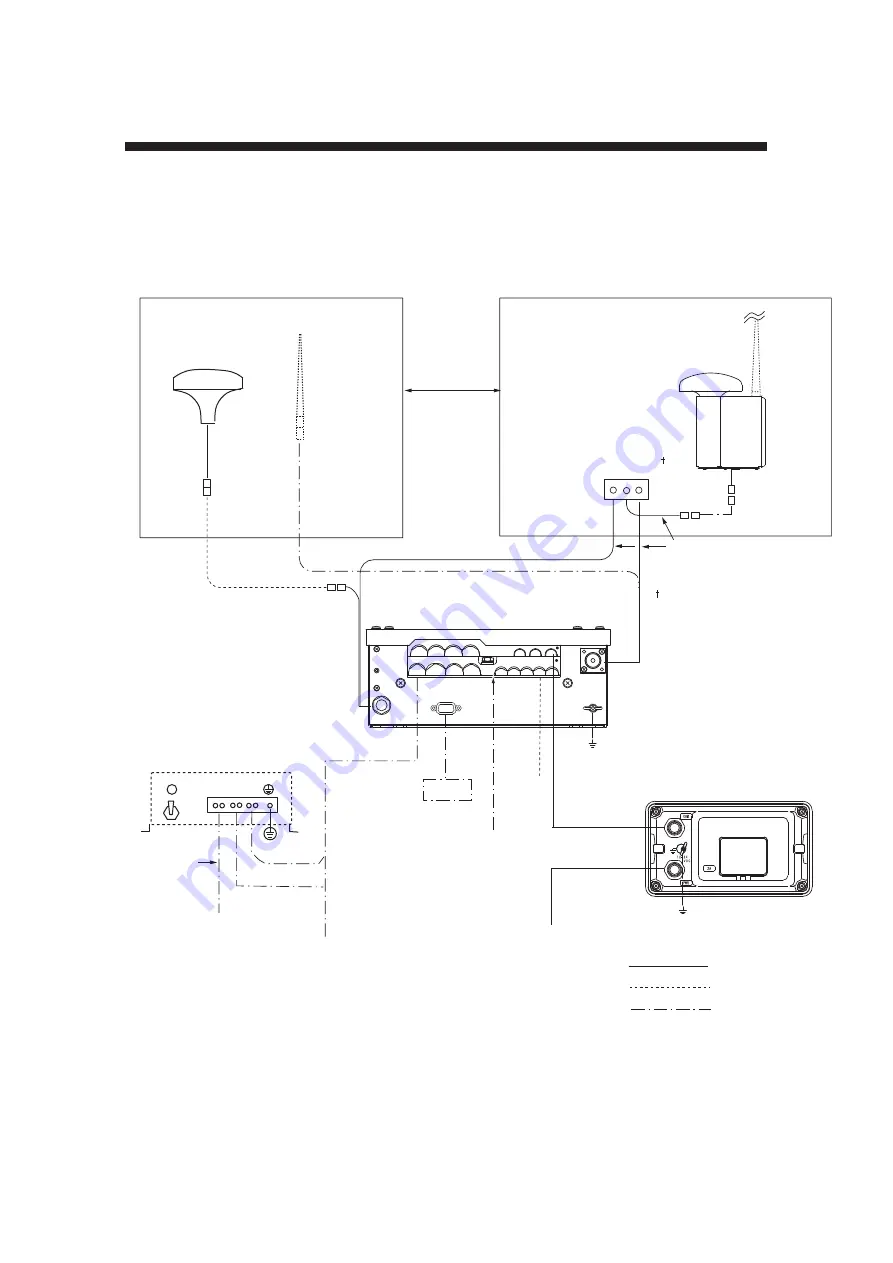
Connect the equipment, referring to the interconnection diagram at the back this
manual.
GPS Antenna
GSC-001 or
GPS-017 S
PC
150M-W2VN
or FAB-151D
Either one
RG-10U/Y
RG-10U/Y
Attached to Distributor
(approx. 1m)
Distributor unit
DB-1
AC
IN
DC
IN
DC
OUT
12-24 VDC
(Connect to the al ternative
power source.)
100/110/115/200/
220/230 VAC
Power Suppl y
PR-240-CE
DPYC-2.5
GPS/VHF Conbined
Antenna GVA-100
8 D-F B-CV, 30 m/50 m: Option
RG-10U/Y: Local suppl y
: Standard
: Option
: Local Suppl y
DPYC-1.5**
0.6 m
*
*
*
0.8 m
: Ground is not req uired.
BREAKER
6.3A
GPS ANT
PC
VHF ANT
Other external device
(See next page.)
Ground
IV-2.0sq
Transponder unit
FA-1501
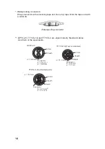
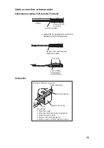
*,**: See page 14.
12-24 VDC
Monitor unit
FA-1502
IV-1.25sq
MJ -A3SPF 0013
3.5m
MJ -A10SPF 0012
5/10/25/50/100m
IV-1.25sq
LAN
Summary of Contents for FA-150
Page 2: ...This page left intentionally blank ...
Page 4: ...This page left intentionally blank ...
Page 5: ...Revision history manual Rev A B C Description Date dd mm yyyy Sign A A 06 05 2015 HAB ...
Page 6: ...This page left intentionally blank ...
Page 8: ...This page left intentionally blank ...
Page 9: ...Index divider Section 1 N ...
Page 10: ......
Page 12: ...PRINTED IN JAPAN UAIS TRANSPONDER FA 150 ...
Page 53: ...Antenna Cable Set CP20 02700 004 381 160 CP20 02710 004 381 170 A 8 ...
Page 54: ...Antenna cable Set CP24 00300 000 041 938 CP24 00310 000 041 939 A 9 ...
Page 55: ...Y Hatai D 1 ...
Page 56: ...Y Hatai D 2 ...
Page 57: ...Y Hatai D 3 ...
Page 58: ...Y Hatai D 4 ...
Page 59: ...Feb 19 03 D 5 ...
Page 60: ...May 20 03 D 6 ...
Page 61: ...Feb 22 05 D 7 ...
Page 62: ...Jan 9 03 D 8 ...
Page 63: ...Mar 11 04 H Hayashi D 9 ...
Page 64: ...Feb 02 05 D 10 ...
Page 65: ...Nov 28 03 D 11 ...
Page 66: ...Oct 02 03 D 12 ...
Page 67: ...H Hayashi Mar 10 05 D 13 ...
Page 69: ...Index divider Section 2 N ...
Page 70: ......
Page 72: ...This page left intentionally blank ...
Page 129: ...Index divider Section 3 N ...
Page 130: ......
Page 187: ...Index divider Section 4 N ...
Page 188: ......
Page 190: ...TECHNICAL MANUAL A100K11209 v 1 3 Sound Reception System VSS V2 Installation User Manual ...
Page 204: ...15 VSS V2 Technical Manual A100K11209 v 1 3 4 7 Cable Connection Diagram ...
Page 206: ...17 VSS V2 Technical Manual A100K11209 v 1 3 5 2 VSS V2 Master Panel Dimensions in mm ...
Page 207: ...18 A100K11209 v 1 3 VSS V2 Technical Manual 5 3 VSS V2 Slave Panel Dimensions in mm ...

