U
lstein Power & Control AS
This document and its content is the property of ULSTEIN. Non-
public information contained herein shall be treated as
Confidential Information. No use, copying, citation or publication
of this document or its content is permitted without prior written
consent from ULSTEIN. Any conflicts arising from unauthorized
use shall be governed by the laws of Norway.
File Name:
BRI-D32004-01II (D)
System Installation
Manual.doc
Page:
Page 12 of
56
2.3.
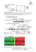
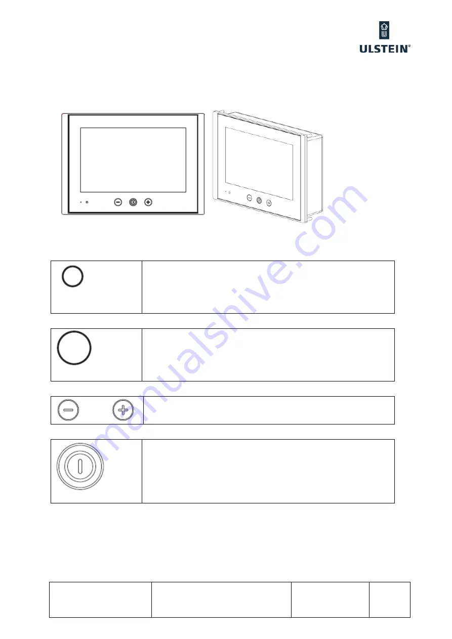
USER CONTROLS OVERVIEW
The units are designed by using HATTELAND® Glass Display Control™ (GDC) touch technology to allow
interactivity adjusting brilliance (brightness) and control power on / off with the use of illuminated symbols. Note
that these symbols are only visible (backlight illuminated) when suitable power is connected. There is no physical
moving knobs, potmeters, wheels or push buttons available as everything is touch surface controlled by Projected
Capacitive technology, that allows a human finger (including several types of gloves) to control the unit.
2.3.1.1.
Light Sensor
Used to sense level of ambient light in the surrounding environment. The sensor
data can be read by suitable software through the Hatteland Display SCOM
functionality of the unit and thus can be used to control brightness remotely.
Note: This sensor is not visible for the eye or has any illumination behind to
indicate it’s position. Further, by touching or covering this area will naturally
make the sensor data inaccurate.
2.3.1.2.
Programmable Alarm LED
Used to indicate an Alarm or similar functionality. The logic to this LED can be
programmed through customized API which gives access to controlling its
function and for instance setup blinking patterns. Note: This LED (when not
activated) is not visible for the eye or has any illumination behind to indicate
it’s position. Further, by touching this area no action will be performed or has
been assigned.
2.3.1.3.
Brightness Adjust
Brilliance / Brightness adjustment of the displayed image is adjusted by
touching the (-) or (+) illuminated symbols.
Both symbols are visible as long as the unit is powered.
2.3.1.4.
Power ON/OFF
Touching this symbol will either turn on or off the unit.
Summary of Contents for FA-150
Page 2: ...This page left intentionally blank ...
Page 4: ...This page left intentionally blank ...
Page 5: ...Revision history manual Rev A B C Description Date dd mm yyyy Sign A A 06 05 2015 HAB ...
Page 6: ...This page left intentionally blank ...
Page 8: ...This page left intentionally blank ...
Page 9: ...Index divider Section 1 N ...
Page 10: ......
Page 12: ...PRINTED IN JAPAN UAIS TRANSPONDER FA 150 ...
Page 53: ...Antenna Cable Set CP20 02700 004 381 160 CP20 02710 004 381 170 A 8 ...
Page 54: ...Antenna cable Set CP24 00300 000 041 938 CP24 00310 000 041 939 A 9 ...
Page 55: ...Y Hatai D 1 ...
Page 56: ...Y Hatai D 2 ...
Page 57: ...Y Hatai D 3 ...
Page 58: ...Y Hatai D 4 ...
Page 59: ...Feb 19 03 D 5 ...
Page 60: ...May 20 03 D 6 ...
Page 61: ...Feb 22 05 D 7 ...
Page 62: ...Jan 9 03 D 8 ...
Page 63: ...Mar 11 04 H Hayashi D 9 ...
Page 64: ...Feb 02 05 D 10 ...
Page 65: ...Nov 28 03 D 11 ...
Page 66: ...Oct 02 03 D 12 ...
Page 67: ...H Hayashi Mar 10 05 D 13 ...
Page 69: ...Index divider Section 2 N ...
Page 70: ......
Page 72: ...This page left intentionally blank ...
Page 129: ...Index divider Section 3 N ...
Page 130: ......
Page 187: ...Index divider Section 4 N ...
Page 188: ......
Page 190: ...TECHNICAL MANUAL A100K11209 v 1 3 Sound Reception System VSS V2 Installation User Manual ...
Page 204: ...15 VSS V2 Technical Manual A100K11209 v 1 3 4 7 Cable Connection Diagram ...
Page 206: ...17 VSS V2 Technical Manual A100K11209 v 1 3 5 2 VSS V2 Master Panel Dimensions in mm ...
Page 207: ...18 A100K11209 v 1 3 VSS V2 Technical Manual 5 3 VSS V2 Slave Panel Dimensions in mm ...


