1. OPERATIONAL OVERVIEW
1-81
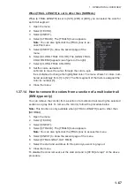
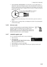
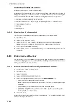
7. Select [4 BARGE ARRANGEMENT]. This item lets you set a single barge or a
barge chain. Spin the scrollwheel to select a value, then left click to move the cur-
sor to the next line. Select number of barges (max. 9) to display. As you spin the
scrollwheel the squares light or extinguish and the number of barges selected ap-
pears at the right side.
You can also use the number keys on the Control Unit to select the number of
barges.
8. Close the menu. The barge mark is now displayed as shown in the example figure
on the previous page.
1.43.6
Antenna mark
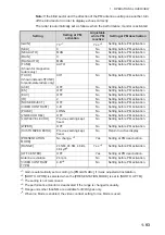
When [2 OWN SHIP MARK] in the [2 MARKS] (for A/B/W-types
with Radar Plotter functionality, this menu appears as [2
MARKS•CHART]) menu is set to [SCALED], the antenna loca-
tion is shown as a blue cross. The location of the antenna, and
therefore the antenna mark, is set at installation.
1.43.7
Latitude/longitude grid
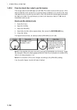
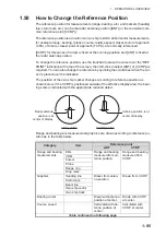
You can show/hide the lat/lon grid to suit your preferences.
1. Open the menu.
2. Select [2 MARK].
For A/B/W-types with Radar Plotter function-
ality
, select [2 MARKS•CHART].
3. Select [0 NEXT] to show the next page.
4. Select [2 GRID], then select [ON] to show the grid, or [OFF] to hide the grid.
5. Close the menu.
4
9
9
9
4
X
First row of barge [ARRANGEMENT] is displayed
as the right side of the barge icon on-screen.
Own ship icon
X
Antenna
mark
MARK (2/2)
BACK
GRID
Summary of Contents for FAR-2218
Page 132: ...1 OPERATIONAL OVERVIEW 1 110 This page is intentionally left blank ...
Page 176: ...3 TARGET TRACKING TT 3 36 This page is intentionally left blank ...
Page 202: ...4 AIS OPERATION 4 26 This page is intentionally left blank ...
Page 232: ...5 VIDEO PLOTTER OPERATION 5 30 This page is intentionally left blank ...
Page 294: ......

