1. OPERATIONAL OVERVIEW
1-4
1.2
How to Turn the Radar On/Off
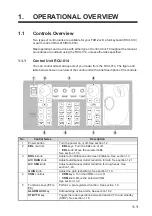
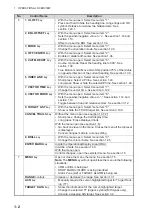
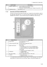
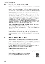
The power button ( ) is located at the top-left corner of the RCU-014 and RCU-015
Control Units.
Note:
The RCU-016 Control Unit has no power button. To turn the power on or off
when using a RCU-016 Control Unit, use the power button on the RCU-014/RCU-015.
To turn the power on, open the power switch cover, then press the power button.
To turn the power off, open the power switch cover, then press the power button.
Note:
Solid state radars do not have a magnetron, therefore they have no warming
period.
1.3
How to Adjust the Brilliance
The screen brilliance (brightness) for monitors can be adjusted as shown below.
Note:
The following procedure applies only to monitors supplied by FURUNO for this
system. For other monitors, see the monitor operator’s manual to adjust the brilliance.
Brilliance adjustment from the Control Unit (RCU-014)
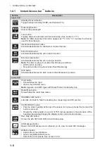
Rotate the
BRILL
knob clockwise to increase the brilliance (brighter), or rotate the
BRILL
knob counter-clockwise to reduce the brilliance (darker).
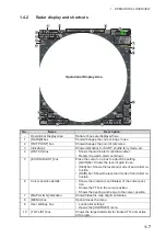
Brilliance adjustment from the on-screen box
Select the [BRILL] box, the spin the scrollwheel on the Control Unit upwards to reduce
the brilliance (darker) or downwards to increase the brilliance (brighter).
Note:
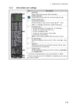
The above scrollwheel operation is based on default
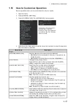
settings for [2 MOUSE WHEEL DIR]. See section 1.10.
The LED to the left of the power button lights up (green color) and the system begins
the startup process. The indication "Initializing......" appears at the center of the screen.
When the startup process is complete, the system begins warm-up procedures to pre-
pare the magnetron for transmission. The warm-up can take up to three minutes.
During the warm-up, indications for total on-time (magnetron on-time since installation)
and total transmission time (since installation) appear below the warm-up countdown
timer. These indications are also displayed when the radar is in standby mode.
When the warm-up process is complete, the radar goes into standby (STBY) mode and
the indication "RADAR STBY" (IMO-types) or "STBY" (A/B/R/W-types) appears. This in-
dication also appears whenever the equipment is in STBY mode.
Note 1: For B/W-types with Radar Plotter functionality
, the “STBY” indication ap-
pears only once, when the equipment is turned on.
Note 2: For B/W-types with Radar Plotter functionality
, the numerals on the heading
dial (outer-most range ring) are not shown and the TT function is inactive while in stand-
by (STBY) mode.
Note 3:
Do not turn on the power directly after it has been turned off. Wait several sec-
onds before you reapply the power, to be sure the radar starts up properly.
[BRILL] box
Summary of Contents for FAR-2218
Page 132: ...1 OPERATIONAL OVERVIEW 1 110 This page is intentionally left blank ...
Page 176: ...3 TARGET TRACKING TT 3 36 This page is intentionally left blank ...
Page 202: ...4 AIS OPERATION 4 26 This page is intentionally left blank ...
Page 232: ...5 VIDEO PLOTTER OPERATION 5 30 This page is intentionally left blank ...
Page 294: ......

