background image

1.  OPERATIONAL OVERVIEW

1-42

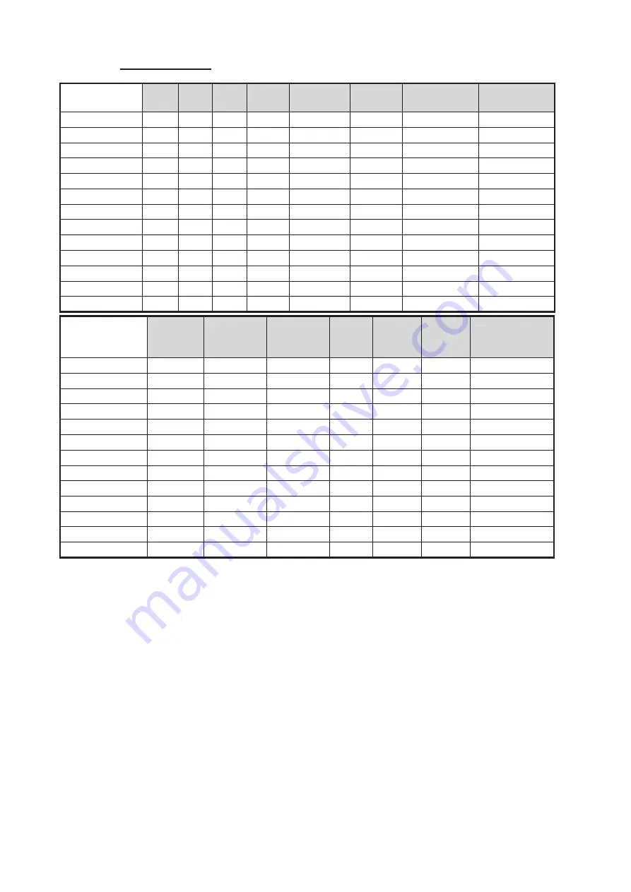
Default settings

*: Available for B/W-type radars only.

IR

ES

EA

NR

AUTO 

SEA

AUTO 

RAIN

TARGET 

ANALYZER*

HATCHING*

CUSTOM1

1

1

1

OFF

MAN-30

MAN-0

OFF

OFF

CUSTOM2

1

1

1

OFF

AUTO-30

MAN-0

OFF

OFF

CUSTOM3

1

1

1

OFF

MAN-30

MAN-0

OFF

OFF

NEAR

1

1

1

OFF

MAN-30

MAN-0

OFF

OFF

FAR

1

2

1

OFF

AUTO-40

MAN-0

OFF

OFF

NEAR BOUY

1

1

2

OFF

MAN-30

MAN-0

OFF

OFF

FAR BUOY

1

2

2

OFF

AUTO-30

MAN-0

OFF

OFF

ROUGH SEA

1

OFF

2

OFF

MAN-50

MAN-40

OFF

OFF

SHIP

1

2

1

OFF

MAN-30

MAN-0

OFF

OFF

HARBOR

1

OFF

1

OFF

MAN-30

MAN-0

OFF

OFF

BIRD

1

OFF

1

OFF

MAN-30

MAN-0

OFF

OFF

ICE

2

OFF OFF

OFF

MAN-30

MAN-0

OFF

OFF

COAST

OFF

OFF OFF

OFF

MAN-30

MAN-0

OFF

OFF

STC 

CURVE

STC 

RANGE

LOW 

LEVEL 

ECHOES

GAIN

ACE

ACE 

GAIN

VIDEO 

CONTRAST

CUSTOM1

3

8

0

85

OFF

50

2-B

CUSTOM2

3

8

0

85

OFF

50

2-C

CUSTOM3

3

8

0

85

ON

50

2-B

NEAR

3

8

0

85

OFF

50

1-B

FAR

3

8

0

85

ON

60

4-B

NEAR BOUY

3

8

0

85

OFF

50

1-C

FAR BUOY

3

8

0

85

OFF

50

4-C

ROUGH SEA

3

9

0

85

OFF

35

2-C

SHIP

3

8

0

85

ON

50

2-B

HARBOR

3

8

0

75

ON

50

1-C

BIRD

3

8

0

85

OFF

50

3-C

ICE

3

7

0

80

OFF

50

1-B

COAST

3

8

0

85

OFF

50

2-C

Summary of Contents for FAR-2218

Page 1: ...2218 FAR 2218 BB FAR 2228 FAR 2228 BB FAR 2238S FAR 2238S BB FAR 2238S NXT FAR 2238S NXT BB FAR 2318 FAR 2328 FAR 2328W FAR 2338SW FAR 2338S FAR 2338S NXT OPERATOR S MANUAL www furuno com Model MARINE RADAR ...

Page 2: ...7KH SDSHU XVHG LQ WKLV PDQXDO LV HOHPHQWDO FKORULQH IUHH 85812 XWKRUL HG LVWULEXWRU HDOHU VKLKDUD FKR 1LVKLQRPL D 3 1 129 3ULQWHG LQ DSDQ OO ULJKWV UHVHUYHG 81 3XE 1R 20 5 5 VHULHV ...

Page 3: ...nd and product names are trademarks registered trademarks or service marks of their respective holders How to discard this product Discard this product according to local regulations for the disposal of industrial waste For disposal in the USA see the homepage of the Electronics Industries Alliance http www eiae org for the correct method of disposal How to discard a used battery Some FURUNO produ...

Page 4: ...e If the antenna unit is installed at a close distance in front of the wheel house your admin istration may require halt of transmission within a certain sector of antenna revolution This is possible Ask your FURUNO representative or dealer to provide this feature Radio Frequency Radiation Hazard WARNING XN12CF 4 ft XN20CF 6 5 ft XN24CF 8 ft SN24CF 8 ft SN30CF 10 ft SN36CF 12 ft Unavailable on IMO...

Page 5: ...quipment Fire or electrical shock can result if a liquid spills into the equipment Do not operate the equipment with wet hands Electrical shock can result Keep heater away from equipment Heat can alter equipment shape and melt the power cord which can cause fire or electical shock Do not disassemble or modify the equipment Fire electrical shock or serious injury can result Immediately turn off the...

Page 6: ...d mass reef ships or other surface vessels but can imply returns from sea surface and clutter As the level of clutter changes with environment the operator should properly adjust the A C SEA A C RAIN and GAIN controls to be sure target echoes are not eliminated from the radar screen The plotting accuracy and response of this TT meets IMO standards Tracking accuracy is affected by the following The...

Page 7: ...19 1 12 2 Manual speed input 1 21 1 13 How to Set the Own Ship Position 1 21 1 14 How to Adjust the Date and Time 1 22 1 15 User Settings 1 23 1 15 1 How to reset the user settings 1 25 1 15 2 How to save load user settings 1 25 1 16 How to Start Stop Transmission 1 26 1 17 How to Tune the Receiver Magnetron Radars Only 1 27 1 17 1 How to select the tuning method 1 27 1 17 2 How to initialize tuni...

Page 8: ...ing 1 53 1 33 1 Methods to measure bearing 1 54 1 33 2 True or relative bearing 1 54 1 34 Collision Assessment by Offset EBL 1 55 1 34 1 How to assess risk of collision using the offset EBL 1 55 1 34 2 How to set the origin point reference for EBL OFFSET 1 56 1 35 How to Measure Range and Bearing Between Two Targets 1 57 1 36 How to Off Center the Display 1 59 1 37 Target Trails 1 60 1 37 1 True o...

Page 9: ...1 45 1 How to select a brilliance and color scheme 1 83 1 45 2 How to change the color and brilliance assigned to a palette 1 83 1 45 3 How to change the color palette 1 85 1 46 How to Display and Set Up Navigational Data 1 86 1 46 1 How to set up the navigational data 1 86 1 46 2 How to display navigational data 1 87 1 47 How to Use the Information Box 1 87 1 48 Interswitch 1 89 1 48 1 How to dis...

Page 10: ...racking 3 1 3 2 TT Controls 3 2 3 3 TT Box Overview 3 2 3 4 How to Select the TT mode 3 3 3 5 How to Acquire and Track Targets 3 4 3 5 1 How to manually acquire a target 3 4 3 5 2 How to automatically acquire targets 3 5 3 6 How to Enter Own Ship Speed 3 5 3 6 1 Echo referenced speed input 3 5 3 7 How to Cancel Target Tracking 3 7 3 7 1 How to cancel tracking for individual TT targets 3 7 3 7 2 Ho...

Page 11: ... perform a trial maneuver 3 28 3 17 3 How to stop the trial maneuver 3 30 3 18 TT System Messages 3 31 3 19 TT Simulation Mode 3 32 3 20 Criteria for Tracking Target Selection 3 33 3 21 Factors Affecting Target Tracking 3 34 4 AIS OPERATION 4 1 4 1 Controls for AIS 4 2 4 2 AIS Box Overview 4 3 4 3 How to Select the AIS Display Mode 4 3 4 4 AIS Symbols and Their Meanings 4 4 4 5 How to Use the AIS ...

Page 12: ...osition 5 2 5 4 Radar Map 5 3 5 4 1 How to show hide radar map marks 5 3 5 4 2 How to select the mark color B W type only 5 4 5 4 3 How to inscribe marks 5 4 5 4 4 How to delete marks 5 6 5 4 5 How to align the radar map 5 7 5 5 Origin Mark 5 8 5 5 1 How to inscribe origin marks 5 8 5 5 2 How to set origin mark stabilization 5 9 5 5 3 How to delete origin marks 5 9 5 6 How to Change the Shape of t...

Page 13: ...Maintenance Schedule 6 2 6 2 How to Replace the Fuse 6 3 6 3 Life Expectancy of Major Parts 6 4 6 4 Trackball Maintenance 6 4 6 5 Easy Troubleshooting 6 5 6 6 Advanced level Troubleshooting 6 6 6 7 Diagnostics 6 8 6 8 Sentence Monitor 6 12 6 9 Fallback Arrangements 6 12 APPENDIX 1 MENU TREE AP 1 APPENDIX 2 LONGITUDE ERROR TABLE 96 NM SCALE AP 9 APPENDIX 3 ALERT CODES MESSAGES MEANINGS AP 11 APPEND...

Page 14: ...dar Solid state radar Viewing distances are as follows MU 190 MU 270W 1020 mm MU 231 1200 mm Two methods of operation are available the standard supply control unit RCU 014 and the optional trackball unit RCU 015 RCU 016 The ergonomically designed palm rest on the track ball unit makes it easy to use Simple operation with point and click menu functionality All functions can be accessed using only ...

Page 15: ...pyright 2015 Ubiquitous Corp All right reserved Portions of this software are copyright 2016 The FreeType Project www freetype org All right reserved This equipment includes GPL2 0 LGPL2 0 Apache BSD MIT or other licensed softwares For further software information please access the following URL https www furuno co jp en contact cnt_oss_e01 html Terminology Meaning or usage example Select Use the ...

Page 16: ...ver W Washington Ferry Function availability and specification type Function Type IMO A B R W TT symbol selection No No Yes No Yes Acquisition zone range limitation Yes No No Yes No Auto Track Target No Yes Yes No Yes Chart Display No Yes Yes No Yes Color Echo No No Yes No Yes Cursor range unit selection No No Yes No No Cursor Size No No Yes No Yes Echo area configuration No No Yes No Yes Mark col...

Page 17: ...erence received simultaneously from multiple radars may be difficult to reduce See section 1 22 Echo stretch Enlarges target echoes especially small echoes Suppress interference sea clutter and rain clutter be fore using echo stretch to prevent enlargement of unwanted echoes See section 1 23 Echo averaging The radar samples echoes with each scan Targets that show a large change with each scan are ...

Page 18: ... VAC 1ø 50 60 Hz USB Mouse Switching Hub HUB 100 Control Unit RCU 014 or RCU 015 Monitor Unit 3 MU 190 or MU 231 or MU 270W Intelligent Hub HUB 3000 5 Gyrocompass 1 AD 10 format Gyrocompass 1 IEC61162 format AIS Transponder EPFS 2 GPS SDME Speed log AMS IEC61162 format Sub monitor 1 of ECDIS 8 Sub monitor 2 of ECDIS 8 AMS Contact 4 Sub monitor Antenna Cable 5 100 115 220 230 VAC 1ø 50 60 Hz for de...

Page 19: ...07 Antenna Unit for FAR 2238S NXT BB 2338S NXT 250 W w Performance Monitor PM 52B 7 SN24CF RSB133 111 11 SN30CF RSB133 111 11 SN36CF RSB133 111 Sub monitor 1 of ECDIS 8 Sub monitor 2 of ECDIS 8 Control Unit RCU 014 or RCU 015 Control Unit RCU 016 Standard supply Optional or local supply USB Device 9 USB Mouse 100 230 VAC 1ø 50 60 Hz Transformer 440 VAC 1ø 50 60 Hz Switching Hub HUB 100 Monitor Uni...

Page 20: ...erformance Monitor PM 32A XN20CF RSB130 XN24CF RSB130 Wave guide Signal cable Sub monitor 1 of ECDIS 8 Sub monitor 2 of ECDIS 8 Control Unit RCU 014 or RCU 015 Control Unit RCU 016 Standard supply Optional or local supply USB Device 9 USB Mouse 100 230 VAC 1ø 50 60 Hz Transformer 440 VAC 1ø 50 60 Hz Switching Hub HUB 100 Monitor Unit 3 MU 190 or MU 231 or MU 270W Intelligent Hub HUB 3000 5 100 230...

Page 21: ... PM 52A SN36CF RSB131 Coaxial cable Signal cable Processor Unit RPU 025 Sub monitor 1 of ECDIS 8 Sub monitor 2 of ECDIS 8 Control Unit RCU 014 or RCU 015 Control Unit RCU 016 Standard supply Optional or local supply USB Device 9 USB Mouse 100 230 VAC 1ø 50 60 Hz Transformer 440 VAC 1ø 50 60 Hz Switching Hub HUB 100 Monitor Unit 3 MU 190 or MU 231 or MU 270W Intelligent Hub HUB 3000 5 100 230 VAC 1...

Page 22: ...ation operation and viewing distance of other monitor see its manuals For BB type a monitor unit is prepared by user 4 Characteristics of contact output for Alarm Load current 250 mA Polarity Normally Open 2 ports Normally Close 2 ports Serial I O for alarm is also possible which complies with IEC 61162 1 5 For configurations with 3 or more radars ECDIS FMD 3100 FMD 3200 FMD 3300 connect ed connec...

Page 23: ...ction 1 33 3 BRILL knob Adjust echo brilliance and screen brilliance See section 1 3 A C RAIN knob Adjust auto manual clutter reduction for rain See section 1 21 A C SEA knob Adjust auto manual clutter reduction for rough seas See section 1 20 GAIN knob Adjust the gain sensitivity See section 1 19 4 VRM controls VRM keys Turn the VRMs on or off VRM knob Move the selected VRM See section 1 32 5 Fun...

Page 24: ...egative value to See section 1 14 and section 1 10 Toggle between true and relative vectors See section 3 12 9 TARGET LIST key With the menu open Select menu item 9 Show or hide the TT AIS target list See section 3 10 3 CANCEL TRAILS key Without the menu open see section 1 37 2 Short press Change the trail display time Long press Erase displayed trails With the menu open see section 1 5 Go back on...

Page 25: ...p the selected AIS target Long press Cancel tracking for all TT targets See section 3 2 8 Trackball controls See section 1 1 2 No Control Name Description 1 Power button Turn the power on or off See section 1 2 2 Functions keys F1 to F4 Perform a pre registered function See section 1 9 3 Right mouse button Short press Show the pop up menu for the highlighted item Cancel changes to the currently se...

Page 26: ...se the brilliance brighter Note The above scrollwheel operation is based on default settings for 2 MOUSE WHEEL DIR See section 1 10 The LED to the left of the power button lights up green color and the system begins the startup process The indication Initializing appears at the center of the screen When the startup process is complete the system begins warm up procedures to pre pare the magnetron ...

Page 27: ... screen display for your radar system is divided into three main areas as shown in the figure below 1 InstantAccess bar See section 1 4 1 2 Radar display and function boxes See section 1 4 2 3 Information and settings See section 1 4 3 Display specifications MU 190 MU 231 MU 270W Nominal viewing distance 1 02 m 1 20 m 1 02 m Text height min font 3 53 mm 4 23 mm 3 64 mm Text width min font 2 36 mm ...

Page 28: ...e ACE Auto Clutter Elimination function Lower Half Chart button Shows hides the chart Opens the CHART menu Note Appears on A B W types with Radar Plotter functionality only Radar Map button Shows hides the radar map marks HEADING LINE button Left click and hold to hide the heading line range rings and OS symbol CU TM RESET button Puts the ship s heading at the top of the screen in course up mode t...

Page 29: ... box to adjust the setting GAIN bar Shows the level of gain in use SEA bar Shows the level and mode of sea clutter re duction RAIN bar Shows the level and mode of rain clutter re duction 6 Cursor position details Shows the location coordinates of the cursor posi tion Shows the TTG to the cursor position Shows the bearing and range to the cursor position 7 MAP ALIGN indication Shows hides the map a...

Page 30: ... section 1 17 Adjusts the tuning manual only See section 1 17 3 Note The TUNING LEVEL bar is not shown for solid state radars 19 PICTURE box Selects a preset custom display Right click to open the CUSTOMIZED ECHO menu 20 ANTENNA SELECTION box Selects the antenna to use for radar images Right click to open the SELECT ANTENNA menu 21 CONTROL box Indicates which Dual Radar image is currently selected...

Page 31: ...s Shows the currently selected menu Shows navigational data Shows the performance monitor graph Shows the zoomed area Note TT AIS data are hidden when the menu is open 4 TT AIS settings Contains settings for vectors CPA TCPA lost targets trails etc 5 Alert box Shows active alerts and contains the buzzer silence button and a shortcut to the alert list 6 Guidance box Shows operational guidance for t...

Page 32: ... 2 Roll the scrollwheel to select a menu item then left click The menu item currently selected is highlighted and shown in reverse video You can also select a menu item by pressing the corresponding numeric key on the control unit Echo processing functions Manages marks and tracks Navigation tools PI lines EBL VRM Sets target alarm functions Sets TT and AIS functions Manages stored data Sets data ...

Page 33: ... In this case the currently displayed page is indicated in brackets to the right of the menu title To view the next page of a menu select 0 NEXT To go back one layer or page in the menu left click 1 BACK or right click 4 Roll the scrollwheel to select the desired setting then left click The selected set tings is highlighted and displayed in reverse video In the above example the selected setting a...

Page 34: ...s example place the cur sor on the palette indication displayed as PLTx where x is the currently selected pal ette number inside the brilliance settings box at the bottom left of the screen The selected item appears highlighted with a light blue colored box Right click to show the BRILL1 box menu Similar shortcuts are available from the follow ing on screen boxes indications PICTURE box AIS box TT...

Page 35: ...p 3 5 To quit the selected function right click when the guidance box shows XX EXIT XX function selected The table below lists the contents of the cursor context menu with a brief descrip tion for each menu item Menu Item Description Page 1 TARGET DATA ACQ TT Acquires target displays data for selected tracked target AIS Activates sleeping AIS target displays data for selected AIS target TARGET CAN...

Page 36: ... Y co ordinates display the Y axis is the upper lower half of the screen the upper half of the screen is plus and the lower part of the screen is mi nus The X axis is the left right side of the screen right is plus left is minus Note 2 Cursor data reads when the cursor is placed outside the operational display area Page 2 TARGET DATA ACQ SETTING Change target tracking settings TARGET CANCEL SETTIN...

Page 37: ... cursor with latitude longitude Appears for B types only 6 Close the menu 1 9 How to Set Up Function Keys Some menu functions and menus can be assigned to a function key This allows one touch access to the assigned function or menu To activate an assigned function press the corresponding function key F1 F2 F3 or F4 The current presets are listed at the bottom of the menu page and the function keys...

Page 38: ...RANGE PM SART ECHO TRAIL TRAIL T R WIPER 1 ACE ACE HIGH SENSITIVITY STD KEY ALERT ACK STBY TX HL OFF EBL OFFSET ORIENTATION MODE OFF CENTER CU TM RESET PI LINE VECTOR TIME VECTOR MODE TARGET LIST BRILL MARK MENU RANGE UP RANGE DOWN ACQ TARGET DATA TARGET CANCEL TT AIS TT DISP AIS DISP TARGET DATA ACQ PAST POSN INTER VAL REF MARK CPA LIMIT CPA TCPA AZ1 AZ2 TARGET LIST SORT TRIAL MANEUVER TRIAL MODE...

Page 39: ...ed in heading direction COURSE Vector is displayed in course direction 5 STERN UP RM Select ON to show STERN UP RM orientation in the selection cycle See section 1 30 Note This item is shown for A B W types only 6 SHUTTLE FERRY Sets the shuttle ferry mode to use OFF Shuttle ferry mode is deactivated MODE1 Shuttle ferry mode is activated See Shuttle ferry mode on next page MODE2 Shuttle ferry mode ...

Page 40: ...variations Standard display SHUTTLE FERRY is set to OFF and reversed display SHUTTLE FERRY is set to MODE1 or MODE2 When the display is reversed for shuttle ferry mode the following changes also occur Page 2 2 AUTO COURSE UP RESET Select ON to enable or OFF to disable the automatic reset of the screen when using COURSE UP orientation and your course is more than 22 5 to either side the center of t...

Page 41: ... If the refresh rate is too long the ability to follow courses lessens thereby affecting the per formance of echo averaging trails and TT Note 2 For IMO types Where the heading source is other than the heading sensor for example and EPFS device the sensor indication is displayed in yellow color 1 12 How to Set Own Ship s Speed The TT and azimuth stabilized presentation modes require own ship speed...

Page 42: ...ip speed readout at the top of the screen will be blank In the event of a log error enter speed manually If a speed log is selected as the data source and there is no signal present for 30 seconds the SPD is shown as kn and the label NO LOG BT SIGNAL or NO LOG WT SIGNAL in yellow orange appears and the alert buzzer sounds When the speed input in use is interrupted or lost the system automatically ...

Page 43: ...menu 2 Select 7 INFORMATION BOX 3 Select 2 OWN SHIP INFO 4 Select 4 OWN SHIP POSN Note You can also access the OWN SHIP POSN menu from the on screen box Place the cursor on the POSN X indication in the position box at the top right of the screen then right click 5 Select 2 POSITION SOURCE or 3 MANUAL L L INPUT as appropriate 6 If 2 POSITION SOURCE is selected at step 2 select the appropriate posit...

Page 44: ...t 4 SIO DATA LAN OUTPUT 2 Select ON to share data To disable OS POSN data sharing select OFF Note A navigational aid must be selected at 2 POSITION SOURCE to share OS POSN across the same network 9 Close the menu 1 14 How to Adjust the Date and Time Date and time are displayed at the top right of the screen in the DATE TIME box You can left click the date time format indication to toggle between U...

Page 45: ...not shown in the table below maintain their previous setting The unit can store two separate user settings for the functions listed below in the in ternal memory These settings can also be recalled Functions not shown in the table below cannot be stored or recalled Function Setting s Menu On screen box GAIN Maintained as per previous setting GAIN box SEA AUTO SEA box RAIN AUTO RAIN box TUNE AUTO T...

Page 46: ...de Parallel or Perpendicular MAIN MENU o 3 NAV TOOLS o 2 PI LINES o 4 PI LINE MODE Presentation Mode NORTH UP TM PRESENTATION MODE box Stabilization mode Sea Ground EPFS Ground SPEED box o 2 SHIP SPEED Off centering On centering OFF CENTER key 2 Target trails Display time ON 6 MIN TRAIL MODE box Mode TRUE PAST POSN box Past position OFF PAST POSN box Vector mod REL VECTOR box Vector time 6 MIN AZ1...

Page 47: ...The radar map displays the same map as before PILOT SETTING is activat ed 1 15 2 How to save load user settings 1 Open the menu 2 Select 9 INITIAL SETTINGS 3 Select 4 USER SETTINGS 4 Select USER1 2 LOAD or USER1 2 SAVE to recall or save user settings re spectively 5 Select YES 6 Close the menu When loading settings the following points apply If the newly loaded settings cannot be applied to items ...

Page 48: ... a blank sector where transmission is stopped see the Installation Manual for details How to stop antenna rotation Antenna rotation can be stopped using one of the following procedures Turn the antenna switch off Turn antenna rotation off from the menu See installation manual Screen freeze The screen is not refreshed if the screen has frozen An audio alarm is released 30 seconds after a screen fre...

Page 49: ...s initialized at installation Howev er if you feel that the automatic tuning is not func tioning properly re initialize it by following the procedure below 1 Open the menu 2 Select 2 ECHO 3 Select 4 TUNING INITIALIZE The indication TUNE INIT appears in yellow characters at the top of the display during the ini tialization 4 Close the menu 1 17 3 How to tune the receiver manually 1 Select the 48 mi...

Page 50: ...elengths The order in which the pulselengths are cycled is shown in the table below in dicates the default preset for each range setting Note Available pulselengths are restricted depending on the range 1 18 2 How to change the preset pulselength To change the preset pulselength for a range setting follow the procedure below 1 Open the menu 2 Select 1 ECHO 3 Select 2 CUSTOMIZED ECHO Note You can a...

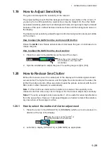
Page 51: ...is 0 to 100 1 20 How to Reduce Sea Clutter Echoes from waves cover the central part of the display with random signals known as sea clutter The higher the waves and the higher the antenna above the water the further the clutter extends When sea clutter masks the picture reduce it with the A C SEA control either manually or automatically Note 1 When both sea clutter and rain clutter are reduced the...

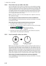
Page 52: ...section 1 20 1 2 Place the arrow on level indicator inside the A C SEA box at the top of the display 3 While observing the A C SEA level indicator spin the scrollwheel to adjust the clutter reduction The setting range is 50 to 50 1 20 3 How to manually reduce sea clutter Note The proper setting of the A C SEA should be such that the clutter is broken up into small dots and small targets become dis...

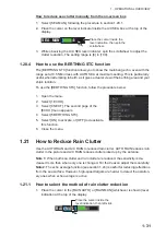
Page 53: ...of the ECHO menu appears 4 Select 5 BERTHING STC 5 Select ON to activate or OFF to deactivate this function 6 Close the menu 1 21 How to Reduce Rain Clutter Use the AUTO RAIN and A C RAIN to reduced rain clutter AUTO RAIN reduces rain clutter in the picture and A C RAIN reduces clutter picked up by the antenna Note 1 When both sea clutter and rain clutter are reduced the sensitivity is de creased ...

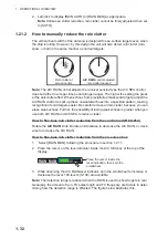
Page 54: ...ou can erase weak echoes Further the possibility of losing weak echoes is greater when you use both A C RAIN and A C SEA to reduce clutter How to fine tune rain clutter reduction from the control unit RCU 014 Rotate the A C RAIN knob Rotate anticlockwise to decrease the A C RAIN or clock wise to increase the A C RAIN How to fine tune rain clutter reduction from the on screen box 1 Select RAIN MAN ...

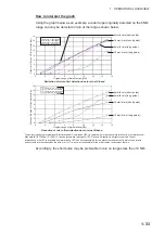
Page 55: ...on NM Original range of first detection NM 16 mm h rain short pulse 4 mm h rain short pulse 16 mm h rain long pulse 4 mm h rain long pulse 16 mm h rain short pulse 4 mm h rain short pulse 16 mm h rain long pulse 4 mm h rain long pulse Reduction of rain to first detection due to rain at S band Reduction of rain to first detection due to rain at X band The author thanks the International Electrotech...

Page 56: ...omly occur ring signals There are three levels of interference rejection depending on the number of transmissions that are correlated You can access this feature from the InstantAccess bar or from the menu The avail able settings are OFF 1 2 or 3 How to reject interference from the InstantAccess bar To adjust the interference rejector select the IR button on the InstantAc cess bar then left click ...

Page 57: ... interference have been sufficiently reduced before activating the echo stretch You can access this feature from the InstantAccess bar or from the menu The avail able options are OFF 1 2 or 3 How to use echo stretch from the InstantAccess bar To set echo stretch select the ES button on the InstantAccess bar then left click to cycle through the settings The available settings in cyclic order are OF...

Page 58: ...1 With echo average active it is harder to detect high speed targets than sta tionary ones Note 2 Do not use the echo averaging function under heavy pitching and rolling loss of targets can result Note 3 Echo averaging requires heading position and speed data Before using the echo averaging function reduce sea clutter with the A C SEA control Leave a little sea clutter on the screen so as not to e...

Page 59: ...the menu How to highlight fast moving targets Normally when echo averaging is in use fast moving targets may be displayed weak ly or not at all The fast target emphasis function highlights fast moving targets but can also highlight sea surface reflections and other noise To use the fast target emphasis function follow the procedure below 1 Open the menu 2 Select 1 ECHO 3 Select 0 NEXT 4 Select 6 E...

Page 60: ...and OFF From the menu 1 Open the menu 2 Select 1 ECHO 3 Select 2 CUSTOMIZED ECHO Note You can also right click the PICTURE box to access this menu 4 Select 0 NEXT 5 Select 4 ACE 6 Select ON or OFF as appropriate 7 Close the menu When ACE is activated the SEA box and RAIN box are gray colored and cannot be adjusted and the echo averaging function is disabled The GAIN box changes to GAIN ACE as show...

Page 61: ...es Note This procedure is only available when the Automatic Clutter Elimination ACE function is ON 1 Open the menu 2 Select 1 ECHO 3 Select 0 NEXT 4 Select 2 ACE 5 Select 3 SUPPRESS SECTOR 6 Spin the scrollwheel or use the number keys to set the start angle for sector sup pression If you use the number keys the cursor moves from left to right When all three dig its are input the cursor moves to th...

Page 62: ...ature automatically reduces the brilliance of weak signals noise sea clut ter rain clutter etc and unwanted signals such as radar interference to clear the pic ture of unwanted echoes Its effect depends on the wiper setting used and whether each averaging is turned on or off as described below Condition A The brilliance of unwanted weak echoes such as noise sea clutter and rain clutter is reduced ...

Page 63: ...ng ACE ACE gain interference rejector echo stretch echo average noise re jector automatic anti sea and anti rain clutter video contrast pulse length and sea and radar conditions Changing these features from the CUSTOMIZED ECHO menu changes the original function key settings To restore the original settings for a particular customize option it is necessary to select the default setting For this rea...

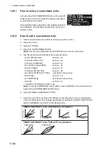
Page 64: ...MAN 50 MAN 40 OFF OFF SHIP 1 2 1 OFF MAN 30 MAN 0 OFF OFF HARBOR 1 OFF 1 OFF MAN 30 MAN 0 OFF OFF BIRD 1 OFF 1 OFF MAN 30 MAN 0 OFF OFF ICE 2 OFF OFF OFF MAN 30 MAN 0 OFF OFF COAST OFF OFF OFF OFF MAN 30 MAN 0 OFF OFF STC CURVE STC RANGE LOW LEVEL ECHOES GAIN ACE ACE GAIN VIDEO CONTRAST CUSTOM1 3 8 0 85 OFF 50 2 B CUSTOM2 3 8 0 85 OFF 50 2 C CUSTOM3 3 8 0 85 ON 50 2 B NEAR 3 8 0 85 OFF 50 1 B FAR ...

Page 65: ...ST M1 M2 M2 M3 M3 L The ICE custom setting sets up the radar to detect areas of ice on the sea surface With ICE active the following restrictions or requirements apply For interswitch configurations with a FAR 2xx8 series as the main radar and a FAR 2xx7 series as the sub radar ice echoes may not appear correctly on the FAR 2xx7 series screen Avoid using a FAR 2xx7 series radar as the interswitch ...

Page 66: ...te To set 2 CONDITION and 4 ACE select 0 NEXT to show the second page of the CUSTOMIZED ECHO menu 6 Select 8 VIDEO CONTRAST TYPE 7 Select 1 2 3 or 4 Dynamic Range or A B C Curve as appropriate Video contrast and curve change depending on setting for VIDEO CONTRAST set at installation as shown in the figure below 2 INT REJECTOR section 1 22 3 ECHO STRETCH section 1 23 4 ECHO AVERAGE section 1 24 5 ...

Page 67: ...tance for STC effectiveness A higher setting eliminates farther surface reflections 14 If necessary select 4 LOW LEVEL ECHO to reject low level echoes The setting range is 0 to 8 The higher the figure the stronger the low level echo that is erased 15 Select 1 BACK to show the second page of the CUSTOMIZED ECHO menu 16 To save custom settings select SAVE from 3 DEFAULT 17 Close the menu 1 28 3 How ...

Page 68: ...T 6 Select FACTORY 1 28 5 How to edit the available customized echoes To edit which customizations are available from the CUS TOMIZE ECHO box follow the procedure below 1 Open the menu 2 Select 1 ECHO 3 Select 0 NEXT 4 Select 3 SELECT CUSTOM The SELECT CUS TOM menu appears 5 Select the customization you want to edit The customizations are listed over two menu pages Select 0 NEXT to see the next pa...

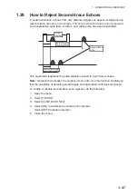
Page 69: ...pment lengthens the pulse repetition period to reject false echoes Note his function decreases the number of echo hits Use this function carefully so that the possibility of detecting small targets and high speed craft does not lessen To enable or disable second trace echo rejection do the following 1 Open the menu 2 Select 1 ECHO 3 Select 3 2ND ECHO REJ 4 Select ON to enable second trace echo rej...

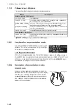
Page 70: ...HEAD UP mode A display without azimuth stabilization in which the line that connects the center with the top of the display indicates your heading Targets are shown at their measured distances and their directions relative to your heading The short dotted line on the bearing scale is the north marker Mode Description Relative Motion RM modes HEAD UP RM Not stabilized STERN UP RM The radar image is...

Page 71: ...ion lies in the orientation of the bearing scale The bearing scale is heading sensor stabilized That is it rotates in accordance with the heading sensor signal enabling you to know own ship s heading at a glance This mode is available when the radar is interfaced with a gyrocompass If the gyro compass fails the bearing scale returns to the state of HEAD UP mode True motion mode Your ship and other...

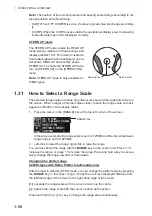
Page 72: ...oser reduce the range scale so that it appears in 50 90 of the display radius 1 Place the cursor in the RANGE box at the top left corner of the screen In the above example the range scale is set to 0 125 NM and the interval between range rings is set to 0 025 NM 2 Left click to lower the range right click to raise the range You can also select the range with the RANGE key on the control unit Press...

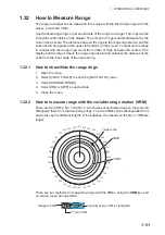
Page 73: ...er edge of the nearest ring 1 32 1 How to show hide the range rings 1 Open the menu 2 Select 3 NAV TOOLS to show the NAV TOOLS menu 3 Select 4 RANGE RINGS 4 Select ON or OFF as appropriate 5 Close the menu 1 32 2 How to measure range with the variable range marker VRM There are two VRMs No 1 and No 2 which appear as dashed rings so that you can distinguish them from the fixed range rings The two V...

Page 74: ... the appropriate VRM box 2 The guidance box reads VRM ON Left click to turn on the VRM The guidance box now reads VRM SET L DELETE Further the box is highlighted and the corresponding VRM appears 3 Left click again and the cursor jumps to inside the operational display area The guidance box now reads VRM FIX L DELETE EXIT 4 Move the trackball to adjust the VRM 5 Left click to anchor the VRM and fi...

Page 75: ... their dashes the dashes on EBL2 are longer Each EBL has an EBRL Electronic Bearing Range Line indicated as a short line crossing the EBL at right angles When VRM is not displayed and only EBL is dis played the EBRL shows the range from the EBL origin When VRMs are displayed with EBLs the VRM overlaps the EBRL The value for EBRL and VRM is the same and is displayed in the VRM box at the bottom rig...

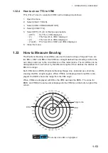
Page 76: ...isects the target of interest then press the left button to anchor the EBL Read the bearing at the lower left corner of the screen 5 Press the EBL OFF key to erase EBLs 1 33 2 True or relative bearing The EBL readout is affixed by R relative if it is relative to own ship s heading T true if it is referenced to the north True or relative indication is available regardless of presentation mode 1 Ope...

Page 77: ...T key and the origin of the active EBL shifts to the cursor position 4 Press the EBL OFFSET key again to anchor the EBL origin 5 After waiting for a few minutes at least 3 minutes operate the EBL knob until the EBL bisects the target at the new position A1 The EBL readout shows the target ship s course which can be true or relative depending on the EBL bearing refer ence setting Note If relative m...

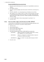
Page 78: ...ing reference setting 6 To return the EBL origin to the own ship s position repeat steps 1 to 3 7 Close the menu 1 34 2 How to set the origin point reference for EBL OFFSET The origin point of the offset EBL can be ground stabilized geographically fixed north stabilized true or referenced to own ship s heading relative 1 Open the menu 2 Select 3 NAV TOOLS 3 Select 3 EBL VRM CURSOR SET 4 Select 2 E...

Page 79: ...en spin the scrollwheel until EBL1 intersects the secondary target Target 2 in the example figure 8 Place the cursor on the VRM1 box then spin the scrollwheel until the range marker on EBL1 aligns with Target 2 The readouts for EBL1 and VRM1 at the bottom of the screen indicate the bearing and range between the Target 1 and Target 2 9 You can repeat the same procedure on third and fourth targets s...

Page 80: ...ng on EBL relative true settings in the EBL VRM menu How to reset the EBL origin to the center of the screen 1 Place the cursor on the box for the EBL to reset then left click The selected EBL is now active and highlighted 2 Place the cursor inside the operational display area then right click The CUR SOR context menu appears 3 Select EBL OFFSET The cursor is now displayed with a red surround 4 Le...

Page 81: ... the operational display area then right click to show the CURSOR menu 2 Select OFF CENTER The cursor is now displayed with a red surround indicat ing that OFF CENTER mode is active 3 Move the cursor to the position where you wish to move the sweep origin then left click The display is now centered at the cursor position Note If you need to move off center position you can reset the off center whi...

Page 82: ...ements in accordance with their over the ground speeds and courses Note The indication in the TRAIL MODE box changes color based on the trail mode and orientation as shown in the following table The reference for the past position displays for AIS and TT is also switched whenever the trail reference is switched 1 Open the menu 2 Select 1 ECHO 3 Select 0 NEXT 4 Select 4 TRAILS The TRAILS menu appea...

Page 83: ...e setting for TRAIL LENGTH in the TRAILS section of the ECHO menu Using the on screen box 1 Place the cursor on the trail time setting inside the TRAIL box at the bottom right of the screen 2 Left click the TRAIL box to change the trail time The options in cyclic order are OFF o 15 sec o 30 sec o 1 min o 3 min o 6min o 15 min o 30 min o CONT o OFF For B W types the available options depend on the ...

Page 84: ...t 4 TRAILS The TRAILS menu appears Note You can also right click the TRAIL box to access this menu 5 Select 3 TRAIL GRADATION 6 Select SINGLE or MULTI Multiple as appropriate 7 Close the menu 1 37 4 Trail level The level or intensity of the afterglow that extends from radar targets can be selected as below 1 Open the menu 2 Select 1 ECHO 3 Select 0 NEXT 4 Select 4 TRAILS The TRAILS menu appears No...

Page 85: ...ure setting the trail time to any interval other than OFF 1 37 7 Trail stabilization in true motion True motion trails can be ground stabilized or sea stabilized The TRAIL box shows current stabilization as TRUE G or TRUE S You can change the stabilization mode with the following procedure 1 Open the menu 2 Select 7 INFORMATION BOX 3 Select 2 OWN SHIP INFO 4 Select 3 SPEED The SPEED menu appears N...

Page 86: ...overed by the dashed circle is erased 6 Release the left button 7 Right click to deactivate the TRAIL ERASER function The cursor is no longer highlighted and the dashed circle disappears 1 37 9 How to prevent sea clutter in true trails You can prevent the display of sea clutter in true trails about your ship to clear the ra dar picture Your ship s trails can also be shown or hidden 1 Open the menu...

Page 87: ...efits Land masses have no trail allowing you to use relative trails near coastlines Only moving echoes create a trail improving target identification 1 Open the menu 2 Select 1 ECHO 3 Select 0 NEXT 4 Select 4 TRAILS The TRAILS menu ap pears Note You can also right click the TRAIL box to access this menu 5 Select 0 NEXT 6 Select 2 HIDE LAND TRAILS T or 3 HIDE LAND TRAILS R as appropriate 7 Referrin...

Page 88: ... SINGLE If you select MULTI the interval between each colored seg ment may be difficult to see clearly 8 Close the menu 1 37 13 How to set the trail color B W type only The setting for trail coloration depends on the setting for 3 TRAIL GRADATION and 4 TRAIL LENGTH as shown in the following table When TRAIL LENGTH is set to NORMAL You can assign one of six colors when 4 TRAIL LENGTH is set to NORM...

Page 89: ...d accordingly from 1 to 12 The first segment of the trails is assigned the color for number 1 9 Close the menu 1 37 14 How to remove the colors from a section of a multicolor trail B W type only You can remove the color s from a section of a multicolor trail leaving the selected section as a gray trail To remove the color s follow the procedure below Note This function is only available when 4 TRA...

Page 90: ...offset the colors follow the procedure below 1 Open the menu 2 Select 1 ECHO 3 Select 0 NEXT 4 Select 4 TRAILS The TRAILS menu appears Note You can also right click the TRAIL box to access this menu 5 Select 0 NEXT to show the second page of the menu 6 Select 6 LONG TRAIL COLOR 7 Select 2 OFFSET TRAIL COLOR 8 To offset the color by one select ON For example if you selected FUSCHIA as the starting ...

Page 91: ...igures show the manner in which this function affects dis played echoes Echo Selected echo color YEL GRN WHT AMB M GRN M CYA Surface reflection Green Green Green Green Green Green Rain Gray Gray Gray Gray Gray Gray Moving target Red Red Red Red Pink Pink Approaching target Pink Pink Pink Pink White White Other echoes Yellow Green White Amber Red to green Red to blue No echo adjustment Target analy...

Page 92: ...nction Note 4 The target analyzer function s performance may be affected by factors such as target size weather and sea conditions physical equipment configuration offset settings and other factors What is hatching Where echo averaging may hide light rain on the display the hatching feature when activated places a gray veil over the areas where rain is detected This allows the operator to see wher...

Page 93: ...A then left click 3 Using the trackball move the cursor to Point B then left click The indication SET is replaced with WORK in the box The target alarm zone s lines are shown as dashed lines Note 1 To create a 360 alarm zone set Point B at the same location as Point A Note 2 Two alarm zones can be set simultaneously The second alarm zone is only available when the first alarm zone is active howeve...

Page 94: ...ted If both zones are active when you try to deactivate zone 1 the system releases two audible beeps and shows the message DELETE ALR2 FIRST 1 39 4 How to change target alarm attributes You can select the echo strength level that triggers the alarm the condition that gen erates the alarm and the volume of the audio alarm as follows 1 Open the menu 2 Select 4 ALERTS 3 Select 6 TARGET ALARM 4 Select...

Page 95: ...e when SET MAXI MUM PI LINES is set to 1 Note 2 For W types PI5 and PI6 are not available 3 Left click to toggle between ON PI line is shown or OFF PI line is hidden 1 40 2 How to set the maximum number of lines to display The maximum number of PI lines available to display depends on your radar type Fur ther the actual number of lines visible can be less depending on line interval IMO A B R types...

Page 96: ...en 000 0 to 359 9 4 Place the cursor on the PI line interval 5 Spin the scrollwheel to adjust the PI line interval A negative interval value moves to the PI line to one side of the line which inter sects the own ship position A positive interval value moves the line to the other side of the own ship position 1 40 4 How to change the PI line bearing reference B W type only IMO A R type radars PI li...

Page 97: ...ine box Place the cursor on the PI line number box indication then press and hold the left but ton From the menu 1 Open the menu 2 Select 3 NAV TOOLS 3 Select 2 PI LINES 4 Select 5 RESET PI LINES The PI lines are reset 5 Close the menu 1 40 7 How to change PI line length IMO A B R types only You can change the length of the PI lines This function is only available when SET MAXIMUM PI LINES is set ...

Page 98: ...awlers for knowing where the net is located Enter the dimensions of your net in the menu to show the net in scale on the display 1 41 1 How to activate the net cursor To activate the net cursor do the following procedure 1 Open the menu 2 Select 3 NAV TOOLS 3 Select 3 EBL VRM CURSOR SET 4 Select 0 NEXT to show the second page of the menu 5 Select NET CURSOR 6 Select NET CURSOR DISPLAY 7 Select ON ...

Page 99: ... WARP LENGTH indication Adjust the values so that the total length for front and rear is equal to or less than 3000m 9 Select 5 NET WIDTH 10 Rotate the scrollwheel then left click to set the net width 11 Select 6 ROTATE STEP Select 360 or 32 POINTS then left click The net cursor moves in the same manner as EBL2 moves Select 360 to move with 0 1 steps or select 32 POINTS to move with 11 25 steps 12...

Page 100: ...lace the cursor and zoom box at the location you wish to zoom then left click to anchor the box If the zoom box is not placed where you intended to place it left click twice then move the box to the correct place Left click to anchor the box 5 Right click to complete the procedure The selected area is displayed on the right side of the screen and the cursor returns to normal shape To disable the z...

Page 101: ...ship press and hold the HL OFF key or place the cursor on the HL OFF box in the InstantAccess bar then left click and hold In addition to the heading line the stern marker and all graphics within the operational display area are also erased To redisplay the heading line etc release the key or the left button 1 43 2 How to hide show the stern mark The stern marker which is a dotted line appears opp...

Page 102: ... dimensions should be entered at installation to use the scaled ship symbol 1 Open the menu 2 Select 2 MARKS For A B W types with Radar Plotter functionality select 2 MARKS CHART 3 Select 2 OWN SHIP MARK 4 Select MINIMIZED or SCALED as appropriate 5 Close the menu 1 43 5 How to set the barge marker You can mark the locations of barges on the display with icons Note This function is not available i...

Page 103: ... 6 Antenna mark When 2 OWN SHIP MARK in the 2 MARKS for A B W types with Radar Plotter functionality this menu appears as 2 MARKS CHART menu is set to SCALED the antenna loca tion is shown as a blue cross The location of the antenna and therefore the antenna mark is set at installation 1 43 7 Latitude longitude grid You can show hide the lat lon grid to suit your preferences 1 Open the menu 2 Sele...

Page 104: ...u appears as 2 MARKS CHART 3 Select 4 DROP MARK 4 Select ON to enable DROP MARK Two indications appear at the bottom of the screen 5 Close the menu 1 44 2 How to inscribe a drop mark 1 Select a drop mark box then left click 2 Place the cursor at the location to inscribe the drop mark then left click The drop mark box shows the range and bearing to the marked location 1 44 3 How to erase drop marks...

Page 105: ...preset for use at night with a gray background To change the current scheme do the following 1 Place the cursor on the PLT indication inside the brilliance settings box at the bottom left of the screen 2 Spin the scrollwheel to show the scheme you want to use then left click You can also left click the indication to cycle through the schemes 1 45 2 How to change the color and brilliance assigned t...

Page 106: ... echoes 3 PALETTE Changes the color scheme see paragraph 1 45 3 4 CONTROL PANEL Adjusts control panel back light brilliance 5 CHARACTERS Adjusts on screen text brilliance 6 CURSOR Adjusts cursor brilliance 7 ECHOES Adjusts the echo brilliance 8 TRAILS Adjusts echo trail brilliance 9 HL Adjusts heading line brilliance Page 2 2 RANGE RINGS Adjusts range ring brilliance 3 BEARING CURSOR Adjusts beari...

Page 107: ...ter brilliance 15 15 15 15 15 15 15 15 Cursor brilliance 15 15 15 12 12 12 12 12 Echo brilliance 15 15 15 12 12 12 12 12 Trail brilliance 15 15 15 8 8 8 8 8 Heading Line brilliance 15 15 15 12 12 12 12 12 Range ring brilliance 15 15 15 7 7 7 15 15 Bearing ring brilliance 15 15 15 6 6 6 15 15 EBL brilliance 15 15 15 12 12 12 12 12 VRM brilliance 15 15 15 12 12 12 12 12 PI Line brilliance 15 15 15 1...

Page 108: ...ION BOX 3 Select 4 NAV DATA SETTINGS 4 Referring to the table below select the appropriate menu item then press the EN TER MARK key 5 Referring to the table above select the appropriate setting then press the ENTER MARK key 6 Close the menu Menu item Available settings Page 1 2 DEPTH OFF ON m ft 3 DEPTH GRAPH SCALE 10 20 50 100 200 500 m 4 DEPTH MARK 000 to 500 m 5 CURRENT OFF ON 6 WIND OFF ON kn ...

Page 109: ... section 1 11 section 1 12 and section 1 13 for details Set up various own ship information such as sensors used for position fix date and time format offsets heading and speed sensors used 3 DISPLAY NAV DATA OFF ON Disable navigational data display Enable navigational data display 4 NAV DATA SETTINGS See section 1 46 for details Set up the format in which various navigational data is displayed in...

Page 110: ...he upper half is overlayed with the newly aquired TT AIS target data When the target data is no longer displayed TT is cancelled etc in the upper box the previous display is restored Each box may display up two TT targets or one AIS target For MU 270W configurations up to three TT targets can be shown Zoom and navigational data are displayed here but can be hidden by TT AIS data Zoom and navigatio...

Page 111: ...lation the processor unit automatically connects to the system as SLAVE when first turned on You can change this setting after the first connection See section 1 48 2 Antenna box ANTx x indicates antenna selected M or S indicates antenna is M aster or S lave X Band or S Band indicates antenna bandwidth The following information is displayed in the SELECT ANTENNA menu Radar band output power and an...

Page 112: ...r displays are automatically changed to slave An antenna unit without a Master display cannot be selected on the sub display units If there is no antenna unit set as master the lowest number display is auto matically set as master If the Alert EXT RADAR ERROR appears do one of the following as applicable If only your antenna is not displayed on the ANT SELECT display the LAN line in the Processor ...

Page 113: ...d as Slave however the maximum displayable range is dependent on the setting at the Master radar Radar Functions Control Master Display Option Slave Display Option AIS function Independent Desired value can be set Desired value can be set Brilliance Echo trails EBL Lat long data Presentation mode Speed data Target alarm TT AIS on off TT AIS track interval Vector mode Vector time VRM Wiper Zoom TT ...

Page 114: ... menu 4 Select 0 CLEAR INTER SWITCH 5 Select YES to clear the interswitch settings The antenna settings are restored to default 1 49 Performance Monitor The performance monitor installed in the antenna unit produces a visual indication on the radar display screen when the radar transmitter power and radar receiver sen sitivity are within the prescribed limits 1 49 1 How to activate deactivate the ...

Page 115: ...ion NOISE REJECT OFF No Setting before PM activation VIDEO CONTRAST 4 B No Setting before PM activation PULSE LONG No Setting before PM activation 2ND ECHO REJ OFF No Setting before PM activation LOW LEVEL ECHO Previous setting kept fixed No Setting before PM activation WIPER OFF No Setting before PM activation CUSTOMIZED ECHO Previous setting kept fixed No Return to active display PRESENTATION MO...

Page 116: ...lect 2 3 5 or 6 as appropriate then press the ENTER MARK key 5 Close the menu The figure belows shows an example where PM ARC is set to 5 Note 1 The lengths of the arcs can vary according to installation environment Judge the strength of the echo that appears within 60 from the arc location to confirm if the radar is working properly or not Note 2 The location of the arcs changes according to the ...

Page 117: ...scrollwheel when the cur sor is placed over the indication The position of the own ship marker changes according to reference position as shown below If the CCRP is positioned outside of the effective display area the bear ing scale is indicated with the appropriate reduced detail Range and bearing are measured and graphics are drawn according to reference po sition as in the table below Category ...

Page 118: ...cknowledged within one minute Also if your vessel returns to within the tolerable radius the alert status is automatically changed to rectified 1 Open the menu 2 Select 4 ALERTS 3 Select 4 ANCHOR WATCH 4 Select ON to enable ANCHOR WATCH then press the ENTER MARK key 5 Spin the scrollwheel to set the distance for the alert Press the ENTER MARK key to apply the setting 6 Close the menu Table continu...

Page 119: ... A B or C according to its degree of severity or source 1 52 2 How to interpret the ALERT box When an alert condition is found the applicable alert message appears in the ALERT box A buzzer sounds for alarm and warning alerts The ALERT box is composed of three lines of text information and several icons as shown below When an Alarm or Warning level alert is released the alert message flashes in th...

Page 120: ...tions are displayed in the list in yellow text in the order in which they appear in the ALERT box To display the alarm list place the cursor on the alert list log button in the ALERT box then left click An unacknowledged alert can be acknowledged from the list by selecting it then left clicking To erase the data for the number selected left click again To refresh the alert list select 9 REFRESH DA...

Page 121: ... warning Active silenced alarm Red flashing Yellow orange flashing Active silenced warning Yellow orange flashing Red flashing Silent Red Silent Red Silent Red Silent Silent Active acknowledged warning Yellow orange Silent Active responsibility transferred warning Yellow orange Silent Rectified unacknowledged warning Yellow orange Silent Caution Yellow Silent 3 short audible alerts repeated every ...

Page 122: ...Rotation to rotate the antenna without transmission The message changes to read Antenna Rotating No TX To stop the antenna rotation left click Stop Antenna Rotation With this feature active and the antenna stopped pushing the STBY TX key on the Control Unit or click the STBY TX button on the Status bar rotates the antenna and transmits pulses Operating one of the above mentioned controls again sto...

Page 123: ...his is the default IMO compliant mode WIDE mode The echoes are displayed in a square area but are not displayed in the data display area ALL mode The echoes are displayed across the entire screen Follow the procedure below to change display modes 1 Open the menu 2 Select 1 ECHO The ECHO menu appears 3 Select 8 ECHO AREA 4 Select the appropriate setting then press the ENTER MARK key 5 Close the men...

Page 124: ...estroy its con tents Make sure the card slot cover is closed unless removing inserting a card Remove or insert a card using only your fingers Do not use metal instruments such as tweezers to remove the card Do not remove the card when data is loading from or saving to the card 1 55 3 Compatible SD cards The table below lists the SD cards that have been verified as compatible for use with this equi...

Page 125: ...the rubber cover 1 55 5 How to remove SD cards Follow the procedure below to safely remove an SD card Note 1 When the system power is turned off skip steps 1 to 3 Note 2 Do not use any instruments tools top insert or remove the SD card 1 Open the menu 2 Select 6 FILES The FILES menu appears 3 Select REMOVE EXT MEDIA then select YES You can now remove the SD card safely 4 Remove the rubber cover on...

Page 126: ...ess is complete the indication COMPLETED appears in the guid ance box and the menu automatically closes 1 55 7 How to read load data from an SD card 1 Open the menu 2 Select 6 FILES The FILES menu appears 3 Select 3 LOAD DATA 4 Select the data to load The indication RD CARD DATA appears during the read process and the menu closes automatically When the process is complete the menu closes automatic...

Page 127: ... regular intervals to remind you to monitor the radar picture for safety or other purposes When the watch alert is enabled the WATCH box appears at the top of the screen When the timer reaches 00 00 an audible alert is released To silence the buzzer click the watch box The timer is reset and begins to countdown again You can reset the timer at any time by clicking the watch box To enable or disabl...

Page 128: ... The manner in which the radar images appear on screen depends on the combination mode selected TT information When a TT target crosses over the boundary line of the display area its information is passed to the other radar display Tracking of the TT continues The TT number changes depending on the number of the antenna which acquires the TT target The lowest numbered Processor Unit assigns TT num...

Page 129: ...witches to Master the other radar is automatically changed to Slave Depending on your level of control available operations are as follows Radar Functions Control Master Slave AIS function Independent Desired value can be set Desired value can be set Brilliance Echo trails EBL Lat long data Presentation mode Speed data Target alarm TT AIS on off TT AIS track interval Vector mode Vector time VRM Wi...

Page 130: ...re removed and tracking stops on the radar which is in stand by However if a TT target is acquired on the radar which is not in standby the TT in formation is passed to the radar which is in standby Changes made to the following functions are applied to both the own radar echoes and the external echoes on the display of the radar which made the changes These settings are not applied to the display...

Page 131: ... all released when dual radar mode is activated Targets acquired and or tracked prior to deactivating dual radar mode are all re leased when dual radar mode is deactivated If either radar enters standby mode all TT targets acquired while the Dual Radar function was active are released removed TT targets can be acquired manually or automatically TT target data sharing be tween the radar in dual rad...

Page 132: ...1 OPERATIONAL OVERVIEW 1 110 This page is intentionally left blank ...

Page 133: ...radar Rmax varies considerably depending on several factors such as the height of the antenna above the waterline the height of the target above the sea the size shape and material of the target and the atmospheric conditions Under normal atmospheric conditions the maximum range is equal to the radar hori zon or a little shorter The radar horizon is longer than the optical one by about 6 because o...

Page 134: ...adiator should be selected for a bearing resolution better than 2 5 IMO Resolution This condition is normally satisfied with a radiator of 1 2 m 4 ft or longer in the X band The S band radar requires a radiator of about 12 feet 3 6 m or longer Range resolution is the ability to display as separate pips the echoes received from two targets that are on the same bearing and close to each other This i...

Page 135: ...s appear on the screen with a prede termined interval and provide a rough estimate of the range to a target The variable range marker s diameter is increased or decreased so that the marker touches the in ner edge of the target allowing the operator to obtain more accurate range measure ments 2 2 False Echoes Occasionally echo signals appear on the screen at positions where there is no target or d...

Page 136: ...nt of the A C SEA control Virtual image A relatively large target close to your ship may be represented at two positions on the screen One of them is the true echo directly reflected by the target and the other is a false echo which is caused by the mirror effect of a large object on or close to your ship as shown in the figure below If your ship comes close to a large metal bridge for example suc...

Page 137: ...ss band of the radar receiver If the SART is within range the frequency match during each of the 12 slow sweeps will produce a response on the radar dis play thus a line of 12 dots equally spaced by about 0 64 nautical miles will be shown When the radar to the SART is reduced to about 1 nm the radar display my show also the 12 responses generated during the fast sweeps These additional dot respons...

Page 138: ...re to turn this feature off when SART detection is no longer your objective 2 3 3 General remarks on receiving SARTs SART range errors When responses from only the 12 low frequency sweeps are visible when the SART is at a range greater than about 1 nm the position at which the first dot is displayed can be as much as 0 64 nm beyond the true position of the SART When the range closes so that the fa...

Page 139: ...X or S band There are several signal formats in general the RACON sig nal appears on the radar screen as a rectangular echo originating at a point just be yond the position of the radar beacon It has a Morse coded pattern Note that the position on the radar display is not accurate 2 5 Radar Target Enhancer RTE An RTE is a radar transponder mounted on navigation buoys and masts of small crafts to s...

Page 140: ...wer transmission power the signal in tensity of closer targets including sea clutter and rain clutter is reduced For this reason when a long range target enters short range the signal intensity ap pears weaker False echoes fore and aft of the target At long range echoes with a strong reflection may appear with a false echo to their fore and aft When the target changes direction the reflection may ...

Page 141: ...C SEA A C RAIN and GAIN controls to be sure target echoes are not eliminated from the radar screen CAUTION CAUTION The plotting accuracy and response of this TT meets IMO standards Tracking accuracy is affected by the following The data generated by TT AIS and video plotter are intended for reference only Tracking accuracy is affected by course change One to two minutes is required to restore vect...

Page 142: ... described in section 3 4 No Indication name Description remarks 1 TT acquisition mode Selects the TT mode see section 3 4 2 Vector time Adjusts the vector time for the selected target 3 Vector reference True Relative referencing for this target s vector 4 Past position time Sets the interval for the target s trail 5 Lost TGT Alert Displays hides the alert when a target is lost ACQ ON MENU OFF VRM...

Page 143: ...isition mode 1 Open the menu 2 Select 5 TT AIS 3 Select 6 TT Note You can also right click TT in the TT AIS box to access this menu 4 Select 2 TT SELECT then select the acquisition condition Your selection here changes how many targets can be acquired both automati cally and manually TT mode selected Indication change MANUAL 100 TT OFF o TT MAN o TT OFF MANUAL 75 AUTO 25 TT OFF o TT MAN AUTO o TT ...

Page 144: ...dule 1 When the target to acquire and the AIS symbol overlap one another right click the operational display area to show the CURSOR MENU then select TT TARGET DATA ACQ to acquire the target 2 Place the cursor on the target to acquire then left click The plotting symbol is drawn by a dashed circle during the initial acquisition stage A vector appears approximately one minute after acquisition The ...

Page 145: ...at the reference mark function is active 3 Place the cursor on a fixed echo such as an island etc at a range of 0 1 to 24 NM from own ship to be used as a reference then left click The cursor changes from the highlighted cross to a circle with dashed lines indicating that the refer ence location is now set See section 3 9 for more information on TT symbols and their attributes The dashed lines of ...

Page 146: ...wrong colli sion avoidance information Further an unstable stationary target produces inaccurate speed data and the target itself may become lost On IMO type radars with AIS in use echo referenced speed is shown in gray to in dicate they are not available for selection When a reference target is lost or goes out of the acquisition range that reference target mark blinks and the indication REF TARG...

Page 147: ...tracked target or tracked target s data to cancel 2 Press the TARGET CANCEL key Using the CURSOR menu Note This methods requires TGT CANCEL SETTING in the second page of the CURSOR MENU to be set as ANY or TT ONLY 1 Right click the operational display area to show the CURSOR MENU 2 Select TARGET CANCEL then left click 3 Select the tracked target to cancel then left click 4 Right click to complete ...

Page 148: ...criteria use the procedure below 1 Open the menu 2 Select 5 TT AIS 3 Select 6 TT 4 Select 7 TT LOST TGT FILTER 5 Select MAX RANGE 6 Select ON The settings can now be adjusted 7 Spin the scrollwheel to adjust the setting as re quired then left click to apply the setting 8 Close the menu Note Reference targets are not affected by this filter 3 8 2 How to enable disable the lost target alert The LOST...

Page 149: ...t 9 INITIAL SETTINGS 3 Select 2 BRILL The BRILL menu appears Note You can also right click the PLT indication to access this menu 4 Select 0 NEXT to show the next menu page 5 Select 7 TT SYMBOLS The set tings are highlighted and can now be adjusted 6 Spin the scrollwheel to select the de sired brilliance then left click to ap ply the setting 7 Close the menu 3 9 2 How to set the symbol color 1 Ope...

Page 150: ...he TT mode provides the full functionality of TT as required by the IMO Resolution A 823 19 and IEC 62288 including display of range bearing course speed CPA and TCPA of all tracked targets The target bearing is shown in relative bearing in the HEAD UP mode and true bearing in the COURSE UP NORTH UP and True Motion modes with the suffix R Relative or T True The target speed and course are shown as...

Page 151: ...n Description Target No Number assigned by the system to this target Target numbers which have become vacant are not re used until the system is restarted or the system tracks more than 100 targets Name Name assigned to this target B W types only Note If the assigned name see section 3 11 is more than six characters in length only the fist six characters of the name appear here BRG Bearing from ow...

Page 152: ...ist appears inside the information box The following operations are available when the list is open How to hide the target list To hide the list do one of the following Place the cursor inside the list then right click Press the MENU key Left click the MENU box Go to next page Click 0 NEXT Go back one page Click 1 BACK Go to the first top page of the list Select 1 BACK then press and hold the left...

Page 153: ...Close the menu Sorting method Description CPA Targets are sorted in order from closest to farthest CPA TCPA Targets are sorted in order from shortest to longest TCPA BCR Targets are sorted in order from closest to farthest BCR BCT Targets are sorted in order from shortest to longest BCT RANGE Targets are sorted in order from closest to farthest range SPEED Targets are sorted in order from fastest ...

Page 154: ...en the menu 2 Select 5 TT AIS 3 Select 6 TT 4 Select 5 TARGET NAME FUNCTION 5 Select ON then press the ENTER MARK key 3 11 2 How to setup preset names 1 Open the menu 2 Select 5 TT AIS 3 Select 6 TT 4 Select 6 TARGET NAME PRESETS 5 Select the appropriate preset The software keyboard appears 6 Referring to section 1 5 2 set the preset name A maximum of six characters may be used for the preset name...

Page 155: ... select 2 TARGET NAME to assign a different name to the target If you select 2 TARGET NAME the software keyboard appears Enter a name for the target then select END The selected name preset or manual input appears at 2 TARGET NAME and is also applied to the on screen target 5 Close the menu Note 1 When a name is assigned to a target the numerical on screen indication is replaced with the assigned ...

Page 156: ...rails from all fixed sta tionary objects possibly producing an unacceptably high level of clutter and masking In such circumstances a ground stabilized display may reduce its effect and enable the observer to detect clearly the trails of moving targets thus enhancing the observ er s situational awareness However the display should be considered only as an approximation of the course and speed made...

Page 157: ...n stationary on the radar screen with vector length zero But in the presence of wind and or current the vectors appear on fixed targets representing the reciprocal of set and drift affecting own ship unless set and drift values are properly entered In the true vector mode there are two types of stabilization ground stabilization TRUE G and sea stabilization TRUE S The stabilization mode is automat...

Page 158: ...ion with any target How to change the vector mode Place the cursor on the vector reference indication in the Vector box then left click to cycle through the following settings REL o TRUE G TRUE S o REL How to change the vector time Place the cursor on the vector time indication in the Vector box then left click to cycle through the following settings 6min o 10min o 20min o 30min o 45min o 60min o ...

Page 159: ...is controlled with TRAIL MODE in the TRAIL context menu To adjust the trail orientation see section 1 37 1 3 13 1 How to display past position points and select the plotting in terval Select the PAST POSN setting then left click to cycle through the following settings OFF o 30sec o 1min o 2min o 3min o 6min o OFF The on screen display of past positions changes in accordance with the selected set t...

Page 160: ...il they lose vectors To enter set and drift do the following 1 Open the menu 2 Select 7 INFORMATION BOX 3 Select 2 OWN SHIP INFO 4 Select 3 SPEED Note You can also right click the SPD box to access this menu 5 Select 4 SET DRIFT 6 Select ON The setting can now be adjusted and SET is selected 7 Spin the scrollwheel to select the appropriate setting Setting range 000 0 to 359 9 then left click The D...

Page 161: ...be adjusted from the ap propriate indication in the TT box 1 Left click the CPA TCPA indication to activate the feature 2 Place the cursor on the indication you wish to adjust 3 Left click or spin the scrollwheel to adjust the settings as required The settings options are outlined in the table below 3 15 2 How to acknowledge the TT collision alarm Press the ALARM ACK key on the control unit or sel...

Page 162: ...ds and the indication TT NEW TARGET or AIS NEW TARGET appears in yellow orange in the Alert Box The symbol of the offending target is red and flashing Further the AIS display is au tomatically turned on if it is off There are two types of acquisition zones available arc and polygon however AZ1 can only be set as an arc Note The acquisition zones are disabled when the setting for 2 AZ ALR SELECT in...

Page 163: ... Polygon zones must have at least three points To set a polygon shaped acquisition zone 1 Place the cursor on the 2 acquisition zone indication at the bottom right of the screen then left click The cursor moves inside the operational display area 2 Place the cursor on the acquisition zone starting point then left click 3 Place the cursor on the second point then left click 4 Repeat step 3 as requi...

Page 164: ...ve when you try to deactivate 1 the system releases an audible alert and shows the message DELETE AZ2 FIRST 3 16 5 How to acknowledge the acquisition zone alert Press the ALARM ACK key on the control unit or select the ALERT box with the trackball then left click to acknowledge the alarm and silence the buzzer 3 16 6 How to select the target type to acquire B W types only You can set the radar to ...

Page 165: ...ector or a polygon having up to 10 points The shape of the No 1 acquisition zone is always a sector 1 Open the menu 2 Select 5 TT AIS 3 Select 2 ACQUISITION ZONE 4 Select 5 AZ POLYGON 5 Select the appropriate setting Shown only for B W type 6 Close the menu Setting Description OFF Acquisition zone is a sector number of points is limited to four Stabilized against land STAB GND Polygon having 3 10 ...

Page 166: ...AREA is selected 1 Select 6 CHECK AREA SETTING 2 Referring to the figure below use the number keys to enter a distance for PORT STBD BOW and STERN You can also spin the scrollwheel then left click to enter these values The area shown in gray is the check area The available setting range for all four values is 0 0NM to 16 0NM The default setting for all four values is 1 0NM Own ship PORT setting PO...

Page 167: ...urses the targets and own ship s future movements are simulated in 0 5 second increments indicating their predicted positions in 30 second intervals as illustrated in the right figure The delay time represents the time lag from the present time to the time when own ship will actually start to change her speed and or course You should therefore take into consid eration own ship s maneuvering charac...

Page 168: ...er To set up and perform a trial maneuver do the following 1 Open the menu 2 Select 5 TT AIS 3 Select 3 TRIAL MANEUVER 4 Select 2 TRIAL MANEUVER 5 Select OFF STATIC or DYNAMIC as appropriate 6 Select 3 SPEED RATE 7 Set the speed rate as required 8 Select 4 TRIAL TURN RATE 9 Set the turn rate for the trial as required Note Two sets of trial speed and trial turn rate combinations are provided This i...

Page 169: ...urse and speed are derived from own ship s cur rent course and speed at the time when the trial maneuver set up starts Setting example for 3 TRIAL SPEED RATE 5 kn 0 15 kn s 10 kn 0 45 kn s Trial speed rate Trial maneuver speed 5 kn First setting 0 15 kn s First setting 0 45 kn s Second setting 10 kn Second setting Setting example for 4 TRIAL TURN RATE 5 kn 1 5 s 10 kn 4 5 s Trial turn rate Trial m...

Page 170: ...r If a maneuver is un safe change speed course and delay until it is safe 18 Highlight the TRIAL status indication then left click The indication changes from SET to show a timer for the trial maneuver and the maneuver begins The trial maneuver takes place with the letter T displayed at the bottom of the screen The time appears at the top right position on the display If any TT is predicted to be ...

Page 171: ...TARGET LOST Warning When the system detects a loss of a tracked target the lost tracked target symbol appears in red and flashes At the same time an au dio alert is produced for one sec ond The lost target mark disappears from the screen after the lost target alert is acknowl edged Confirm the lost target reac quire if necessary REF TARGET LOST Warning When the system detects a loss of a reference...

Page 172: ...ly generated with the relative movement in the following table based on own ship s movement at the start of simulation mode Note If own ship moves after the start of simulation mode the movement of the sim ulated target is not matched with the values in the following table Place the cursor on a target then press the ACQ key to display the target data Acquire the simulated targets after the TT simu...

Page 173: ...not detected in five consecutive scans become lost targets Quantization The entire picture is converted to a digital from called Quantized Video A sweep range is divided into small segments and each range element is 1 if there is radar echo return above a threshold level or 0 if there is no return The digital radar signal is then analyzed by a ship sized echo discriminator As the an tenna scans if...

Page 174: ...Tracking Sea returns If the radar anti clutter control is adjusted properly there is no serious effect because distant wave clutter not eliminated by this control is filtered out by more than one bang correlation and scan to scan matching of data Rain and snow Rain clutter can be acquired and tracked as targets Adjust the rain clutter control to suppress the clutter If it is heavy rain switch to S...

Page 175: ...e targets will however be acquired and tracked when they pass out of the blind zone and again present normal radar echo The an gular width and bearing of any shadow sector should be determined for their influence on the radar In certain cases false echoes in the shadow sector cause the TT system to acquire track and vector them Shadow sectors should be avoided Indirect echoes A target at close ran...

Page 176: ...3 TARGET TRACKING TT 3 36 This page is intentionally left blank ...

Page 177: ...es for the AIS transponder Based on the table below the radar defines which AIS targets are in tracking or lost When you acknowledge a lost target alert the corresponding AIS symbol will be removed from the display An AIS transponder sees all ships fitted with an AIS transponder belonging to either a Class A or Class B AIS Additionally the AIS transponder receives messages from ships and non ships...

Page 178: ...indication of AIS target display capacity limit is given well before it is reached When 95 of 350 targets are displayed the Alert AIS DISPLAY 95 appears When 350 targets are displayed the Alert AIS DISPLAY FULL appears An indication of AIS target processing capacity limit is given well before it is reached The Alert AIS CAPACITY FULL appears when 1 200 targets are in the storage buffer When capaci...

Page 179: ...ing for AIS target display FUNC OFF AIS display is disabled DISP OFF AIS symbols are hidden DISP FILT Only filtered AIS targets are displayed DISP ALL All AIS symbols are displayed 3 VECTOR Adjusts the vector time for the selected target True Relative referencing for this target s vector See section 3 12 for details 4 CPA TCPA Adjusts the CPA TCPA settings 5 AIS CPA Adjusts the AIS auto activate s...

Page 180: ...th the AIS transponder When the AIS function is disabled Above message is prioritized as a Caution level alert for IMO R types A B W types do not show this alert When the AIS function is active Above message is prioritized as a Warning level alert for all radar types 4 5 How to Use the AIS Display Filter If there are too many AIS targets on the screen you may wish to remove unnecessary ones You ca...

Page 181: ... ATON Select ON to hide the corresponding AIS target 8 Close the menu Set the AIS display mode to DISP FILT to show only the AIS symbols selected for display on the AIS DISP FILTER menu Note This function is not available for an activated target Filter type Definition MAX RANGE Any sleeping AIS targets class A B beyond the range set here will not be shown MIN SHIP SPEED Any sleeping AIS targets cl...

Page 182: ...isition beforehand Right click to show the CURSOR menuo 0 NEXT o TGT DATA ACQ SET TING o ANY or AIS ONLY Activate an AIS target from the control unit RCU 014 Put the cursor on the symbol of the AIS target to activate then press the TARGET DATA key Activate an AIS target from the trackball unit Place the cursor on the target you wish to activate for AIS tracking then press the left button SOG Speed...

Page 183: ... the corresponding AIS target 7 Close the menu How to enable disable the AIS auto activate function Use the CPA AUTO ACTIVATE box at the bottom right corner to enable or disable the AIS auto activate function Filter type Definition MAX RANGE Any AIS targets beyond the range set here will not be automat ically activated MIN SHIP SPEED Any AIS targets slower than this setting will not be automatical...

Page 184: ...to show the CURSOR menuo 0 NEXT o TGT DATA ACQ SET TING o ANY or AIS ONLY Sleep a AIS target from the control unit keyboard RCU 014 Place the cursor on the symbol of the AIS target to sleep then press the TARGET CANCEL key Sleep a AIS target with the trackball 1 Place the cursor inside the operational display area then right click The CUR SOR menu appears 2 Select TARGET CANCEL 3 Place the cursor ...

Page 185: ...cess bar skip to step 5 in the below procedure 1 Open the menu 2 Select 5 TT AIS 3 Select 5 AIS 4 Select 6 VOYAGE DATA 5 Select 2 NAV STATUS 6 Spin the scrollwheel to select the navigation status number then left click Nav Status No Meaning 00 UNDERWAY USING ENGINE 01 AT ANCHOR 02 NOT UNDER COMMAND 03 RESTRICTED MANEUVERABILITY 04 CONSTRAINED BY HER DRAUGHT 05 MOORED DEFAULT 06 AGROUND 07 ENGAGED ...

Page 186: ...lwheel to set the number of people on board 0000 to 8191 then left click 17 Close the menu 4 9 How to Display AIS Target Data You can display an AIS target s data by selecting it on the display when the AIS func tion is set for DISP FILT or DISP ALL 4 9 1 AIS pop up information The AIS pop up shows abbreviated AIS data Vessel name COG SOG CPA TCPA and destination for the selected AIS target Simply...

Page 187: ...nd is calculated and displayed as shown below 2 For Class B targets CLASS B appears in place of nav status POSN QLTY value Position accuracy 1 Position 10 m 2 Position with RAIM 10 m 3 Position d 10 m 4 Position with RAIM d 10 m Target s MMSI ID Name of target ship Bearing to target Range to target Target s course Target s speed Target s CPA Target s TCPA Target s bow cross range Target s bow cros...

Page 188: ... and press the TARGET CANCEL key The select target s data is no longer displayed in the data display area Note Navigation status is not available for Class B targets Where the selected AIS target is an aircraft the STATUS box shows the aircraft s altitude 12345678901234567890 1234567 GPS GLONASS POWE DRIVEN VESSEL AHEAD ALONGSIDE 123456789 123456789 25 4m 12345678901234567890 23 59 31 DEC 1 1 EXPA...

Page 189: ...T to show the next menu page 5 Select 8 AIS SYMBOLS The settings are highlighted and can now be adjusted 6 Spin the scrollwheel to select the desired brilliance then left click to apply the set ting 7 Close the menu 4 10 2 How to change the color of the AIS symbol 1 Open the menu 2 Select 5 TT AIS 3 Select 4 TT AIS SYMBOL 4 Select 2 TT AIS SYMBOL COLOR 5 Select the appropriate color 6 Close the me...

Page 190: ...ect 4 TT AIS SYMBOL 4 Select 6 AIS SCALED SYMBOL 5 Select OFF or ON as appropriate OFF All AIS symbols are displayed in the same size ON AIS symbols are displayed in scale according to the ship length The figure above shows examples of standard and scaled symbols 6 Close the menu Standard symbol Scaled symbol ...

Page 191: ...OSN setting then left click to cycle through the following settings OFF o 30sec o 1min o 2min o 3min o 6min o OFF The past positions are displayed in accordance with the selected setting 4 11 2 How to select the number of past position points to be dis played 1 Open the menu 2 Select 5 TT AIS 3 Select 4 TT AIS SYMBOL 4 Select 5 TT AIS PAST POSN POINTS 5 Select 5 or 10 as appropriate 6 Close the me...

Page 192: ... are a lot of AIS targets in your area the lost target alert can sound frequently In this case you may wish to have the alert ignore lost targets whose range speed class or length are below the threshold value you specify 1 Open the menu 2 Select 5 TT AIS 3 Select 5 AIS 4 Select 0 NEXT 5 Select 3 AIS LOST TGT FILTER 6 Referring to the following table select the appropri ate filter 7 Select ON to a...

Page 193: ...t for all lost targets including filtered targets Note The filter setting is applied to both TT and AIS lost targets 4 13 ROT Setting You can set the lower limit of the ROT Rate Of Turn at which the heading line on target symbols will point in direction which the vessel is turning ROT display 1 Open the menu 2 Select 5 TT AIS 3 Select 4 TT AIS SYMBOL 4 Select 4 AIS ROT TAG LIMIT then left click Th...

Page 194: ...t 3 Left click or spin the scrollwheel to adjust the settings as required The settings options are outlined in the table below Indication Method Settings options CPA Left click 0 5 1 0 1 5 2 0 3 0 4 0 5 0 6 0 NM Scrollwheel 0 1 to 20 0 to 10 in 0 1 NM increments 1 NM increments thereafter TCPA Left click 1 2 3 4 5 6 12 15 minutes Scrollwheel 1 to 60 minutes in 1 minute increments Thicker than acti...

Page 195: ... as appropriate to select which symbols and data to display when the associ ation criteria are met Note Association can also be switched on and off from the screen by left clicking the Association Us age icon shown below 7 Referring to the list below set the association criteria Spin the scrollwheel to ad just the value then left click to confirm the setting 8 Close the menu OFF Disable associatio...

Page 196: ...played All default association settings are restored whenever the power is turned on To show the association information place the cursor on the target data box at the right side of the screen then press the ACQ key The selected target s AIS and TT data are displayed together as shown in the examples below Combined TT AIS data for a CLASS A vessel Combined TT AIS data for a CLASS B vessel ...

Page 197: ...C and D at EXT EPFS ANT POSN show the location of the external EPFS antenna calculated in the following manner 5 Close the menu FURUNOMARU Name of your ship Ship s callsign Current location Ship s MMSI number Ship s IMO number Ship s dimensions AIS transponder version Ship and cargo type External EPFS device s installation location Course Speed Positioning source and quality of positioning data He...

Page 198: ...up menu To show the pop up menu select the receiv ing ship s data in the AIS data display area then press the right button 1 Open the menu 2 Select 5 TT AIS 3 Select 5 AIS 4 Select 5 TRANSMIT MESSAGE 5 Select 2 ADDRESS TYPE 6 Select 3 MESSAGE TYPE 7 Select SAFETY for safety messages or BINARY for routine messages 8 For ADDRESSED message do this step For BROADCAST message or if TRANSMIT MESSAGE was...

Page 199: ...ragraph 4 17 1 b Use a file saved in the memory by selecting 5 TRANSMIT MESSAGE fol lowed by 2 OPEN FILE from the second page of the TRANSMIT MESSAGE menu 5 Select 5 TRANSMIT MESSAGE from the second page of the TRANSMIT MES SAGE menu to transmit the message During transmission the message AIS TRANSMITTING appears in the guid ance box The message disappears when the message is sent successfully TRA...

Page 200: ...ws the menu method If you click the AIS mes sage button on the lower half of the InstantAccess bar skip to step 5 1 Open the menu 2 Select 5 TT AIS 3 Select 5 AIS 4 Select 4 SHOW RECEIVED MSGS 5 Select the message to be dis played then left click 6 The message details are displayed below the message list 7 Close the menu 4 17 4 How to set up the AIS mes sage notification 1 Open the menu 2 Select 5...

Page 201: ... shorter AIS DISPLAY FULL Warning The radar only displays the closest 350 AIS targets from own ship ACTIVE AIS FULL Warning Number of active AIS targets has reached 50 AIS COM ERROR Warning Not receiving AIS data from own AIS VDO message Note When no AIS data is received the message AIS COM ERROR appears in the Alert Box Check connection with the AIS transponder When the AIS function is disabled A...

Page 202: ...4 AIS OPERATION 4 26 This page is intentionally left blank ...

Page 203: ...n the true motion mode the own ship mark is automatically returned stern ward 75 from the screen center when it reaches a location 50 of the display radius To select an orientation mode see section 1 30 Marks can be entered at any location inside the operational display area however no mark can be entered at the location of an on screen box A total of 20 000 marks can be inscribed at any one time ...

Page 204: ...RT 3 Select 5 RADAR MAP The RADAR MAP menu appears Note You can also right click the MARK box to open the RADAR MAP menu 4 Select 4 MARK POSITION 5 Referring to the table below select the appropriate location How to set the co ordinates Where 4 MARK POSITION is set to L L the co ordinates settings are dis played Co ordinates can be set one digit at a time as shown in the figure below 1 Spin the sc...

Page 205: ...e the menu A radar map is a combination of map lines and symbols whereby the user can define and input the navigation data route planning and monitoring data The radar map can contain 20 000 points of data Inscribed marks are retained when the power is turned off The radar map is referenced to the WGS 84 datum and appears only when there is valid position data input The radar map does not affect a...

Page 206: ...erent Where 4 MARK POSITION is set to CURSOR 1 Referring to section 5 2 select the mark type you want to use 2 Place the cursor on the MARK box at the bottom left of the screen 3 Spin the scrollwheel to select the appropriate mark then left click The cursor moves inside the operational display area 4 Place the cursor on the location inside the operational display area you wish to inscribe the mark...

Page 207: ...DAR MAP menu appears and the first digit of the latitude is selected 4 Referring to section 5 3 set the latitude and longitude 5 Repeat steps 1 to 3 for multiple mark inscription or right click to complete the pro cedure Note You can see the number of radar map marks lines used on the RADAR MAP menu MENU o 2 MARKS o 5 RADAR MAP Appears as 2 MARKS CHART for A B W types with Radar Plotter functional...

Page 208: ...leted a line segment put the cursor on the starting point or end point To delete consec utive line segments put the cursor on the connecting point 4 Repeat step 3 to delete another mark or press the right button to return the cur sor to normal function How to delete all marks 1 Open the menu 2 Select 2 MARKS For A B W types with Radar Plot ter functionality this menu appears as 2 MARKS CHART 3 Sel...

Page 209: ... are not re aligned when the MAP ALIGN function is activated How to disable the map alignment 1 Right click the operational display area to show the CURSOR MENU You can also place the cursor in the operational display then spin the scrollwheel to show MAP ALIGN L OFF EXIT in the guidance box then left click 2 Select MAP ALIGN then left click The cursor is now highlighted and the MAP ALIGN function...

Page 210: ...een 3 Spin the scrollwheel to select the origin mark to inscribe 4 Click the MARK box 5 Click the location where to put the origin mark The origin mark is inscribed at the location selected To re inscribe the origin mark at a different location click the desired location for the mark 6 To enter an origin mark at another location spin the scrollwheel to change the or igin mark then click the desire...

Page 211: ...g sea stabi lized 1 Open the menu 2 Select 2 MARKS For A B W types with Radar Plotter functionality this menu appears as 2 MARKS CHART 3 Select 5 RADAR MAP The RADAR MAP menu appears Note You can also right click the MARK box to open the RADAR MAP menu 4 Select 2 ORIGIN MARK STAB 5 Select GND or SEA as appropriate 6 Close the menu 5 5 3 How to delete origin marks Unlike other marks you can only de...

Page 212: ...IP SHAPE 2 Put the cursor in the MARK box at the bottom of the screen 3 Spin the scrollwheel to select the point no to change The cursor movies to the selected point position 4 Use the trackball to move the point to the position desired then click Point position information appears in the MARK box as shown in the figure be low 5 Repeat steps 3 to 4 to adjust other points 01 03 04 05 06 07 08 10 09...

Page 213: ...propriate item 2 USER CHART Shows hides received user charts 3 CURVED EBL Shows hides the received Curved EBL 4 CHART SYMBOL Shows hides the re ceived chart symbols 5 NOTE BOOK Shows hides the received notes ON shows notes only when they are received DISPLAY shows notes continuously The notes are shown in the information box at the right side of the screen 6 ROUTE Shows hides the received route CE...

Page 214: ...tionality this menu ap pears as 2 MARKS CHART 5 8 1 How to show hide tracks You can show or hide tracks for own ship or for targets A B W types only 1 Open the menu 2 Select 2 MARKS For A B W types with Radar Plotter functionality select 2 MARKS CHART 3 Select 7 TRACKS 4 Select 2 OWN TRACK or 3 TARGET TRACK as appropriate Note 3 TARGET TRACK is available only for A B W type radars 5 Select 2 DISPL...

Page 215: ...k recording times Note To hide own ship or target past tracks set the interval to OFF To hide both tracks set the interval for both own ship and targets tracks to OFF Tracks plot ted after the setting is set to OFF are hidden Previously plotted tracks remain on screen 7 Close the menu Interval Max Recording Time Interval Max Recording Time 10 s 56 hours 3 min 1000 hours 30 s 167 hours 6 min 2000 h...

Page 216: ...atically plot target tracks for TT target numbers 001 to 015 Note 1 3 SAVE INTERVAL must be set to other than OFF to show tracks Note 2 When this feature is active only the tracks TT targets 001 through 015 are plotted 1 Open the menu 2 Select 2 MARKS For A B W types with Radar Plotter functionality select 2 MARKS CHART 3 Select 7 TRACKS 4 Select 3 TARGET TRACK 5 Select 5 AUTO TARGET TRACK 6 Selec...

Page 217: ...pe radars 5 Select the percentage of the track you wish to delete then left click The available options are 30 50 80 or ALL 6 Close the menu How to erase tracks by color For A B W types only 1 Open the menu 2 Select 2 MARKS For A B W types with Radar Plotter functionality select 2 MARKS CHART 3 Select 8 DELETE DATA 4 Select 5 OS TRACK COLOR TIME or 6 TGT TRACK COLOR TIME 5 Select the color of the ...

Page 218: ... Use Waypoints A particular location is known as a waypoint whether it be a starting point a desti nation point or an intermediate point on a voyage This radar system can store 200 waypoints Waypoints 1 to 198 are user set waypoints waypoint 199 is reserved for external input waypoint 200 is reserved for MOB Man Over Board Waypoints can be entered with the cursor or from the menu manual input of l...

Page 219: ...u Note Waypoints which are part of a route that is currently in use cannot be edited 1 Open the menu 2 Select 8 NAVLINE WPT 3 Select 2 WPT SET 4 Select 2 WPT NO SELECT 5 Spin the scrollwheel or use the control unit num bered keys to select a waypoint number 6 To edit or input a waypoint name select 3 WPT NAME then left click The software keyboard ap pears Referring to section 1 5 2 name the way po...

Page 220: ...deactivate the mark delete func tion How to erase a waypoint from the menu 1 Open the menu 2 Select 8 NAVLINE WPT 3 Select 6 WPT SET 4 Select 2 WPT NO SELECT Then select the waypoint to erase 5 Select 5 CLEAR DATA 6 Select YES or NO as appropriate then left click 7 Close the menu How to erase all waypoints You can erase all waypoints from the menu If there is an active route this procedure cannot ...

Page 221: ...as appropriate 4 Select ON to show the waypoint name number or OFF to hide the waypoint name number then left click he waypoint number and or waypoint name appear to the right of the waypoint mark 5 Close the menu Displayed page Total no of pages Click while on page No 1 to close the list Click while on page No 2 or after to go back on page Long push the left button to go to page No 1 WPT No WPT n...

Page 222: ... Select 8 NAV LINE SET The NAV LINE SET menu appears 4 Select 2 SELECT NAV LINE 5 Spin the scrollwheel or input the number from the keyboard to assign a number to the route The in put areas for 3 NAV LINE 4 NAV LINE ENTRY and 5 CLEAR DATA become active 6 Select 3 NAV LINE NAME 7 Referring to section 1 5 2 assign a name to the route You can use up to 15 characters in the name 8 Select 4 NAV LINE EN...

Page 223: ...lect NAV LINE SELECT 6 Spin the scrollwheel to select the desired route number then left click 7 Select the direction you want to navigate the route in FORWARD Navigate the route in the direction in which it was created REVERSE Navigate the route in reverse of the direction in which it was created 8 Close the menu How to skip a waypoint On a voyage similar to the below example you may want to skip...

Page 224: ...o set a width for the route To disable the route width alert and hide the route width lines set the width to 0 00 NM Note This width is applied to all routes 5 Close the menu How to show hide the turning line You can show or hide the turning line the point at which your vessel starts a turn in a route 1 Open the menu 2 Select 8 NAVLINE WPT 3 Select 0 NEXT 4 Select 3 TURNING LINE 5 Select the appro...

Page 225: ...l routes 1 Open the menu 2 Select 2 MARKS For A B W types with Radar Plotter functionality select 2 MARKS CHART 3 Select 8 DELETE DATA 4 Select 4 ALL NAV LINES 5 Select YES to delete all internal routes 6 Close the menu 5 10 4 How to view the routes list Routes saved to the internal memory can be view by following the procedure below 1 Open the menu 2 Select 8 NAVLINE WPT 3 Select 9 NAVLINE LIST T...

Page 226: ...e next destination For type radars only you can also set a waypoint arrival alert Note To use this alert set 2 NAV LINE DATA SOURCE in the NAV LINE WPT menu to EXT DATA or INTERNAL DATA before hand See section 5 9 1 for details To set and use the waypoint arrival area function follow the procedure below 1 Open the menu 2 Select 8 NAVLINE WPT 3 Select 0 NEXT The second page of the NAVLINE WPT menu ...

Page 227: ... show hide the chart Show hide the chart using the InstantAccess bar Click the Chart button to toggle between CHART ON shows the chart and CHART OFF hide the chart Show hide the chart from the menu 1 Open the menu 2 Select 2 MARKS CHART 3 Select 0 NEXT to show the next page of the menu 4 Select 6 CHART DISPLAY 5 Select ON to display the chart or select OFF to hide the chart then left click 6 Close...

Page 228: ...t The following items are also re aligned when the MAP ALIGN function is activated Display indications unaffected by map alignment The following items are not re aligned when the MAP ALIGN function is activated Chart Icons Meaning Suitable chart scale Unsuitable chart scale Press the ZOOM IN or ZOOM OUT key to adjust the chart scale No chart file Note 1 When you activate or deactivate the MAP ALIG...

Page 229: ...f the following charts then left click VECTOR Navigational chart data by FURUNO FISHING Fishing chart that shows detailed depth contours C MAP Select this when installing C MAP chart data NAVIONICS Select this when installing Navionics chart data 6 Close the menu Note Depth contours for FISHING are drawn differently from navigational chart data bathymetric chart data The FISHING chart does not hav...

Page 230: ...N Note When NAV AIDS is set to OFF no navigational aid data is displayed re gardless of the individual setting for each navigational aid Navigational aid data see following tables Turns each mark on or off To dis play MARINE FARM select LINE or LINE SYMBOL The mark display for light sector differs according to the setting of light beacon For details see the table below Mark name Display example Ma...

Page 231: ... Open the menu 2 Select 9 INITIAL SETTINGS 3 Select 8 UPDATE CHART The confirmation message OTHER FUNCTIONS WILL STOP DURING THE CHART UPDATE ARE YOU SURE appears 4 Select RUN to access the CHART ADMINISTRATION menu 5 Select 6 BASECHARTS SYMBOLS VERSION The version information for your charts and symbols appears 6 Right click to go back to the CHART ADMINISTRATION menu 7 Select 7 CLOSE The confirm...

Page 232: ...5 VIDEO PLOTTER OPERATION 5 30 This page is intentionally left blank ...

Page 233: ...antenna unit Post a warning sign near the switch indicating it should not be turned on while the antenna unit is being serviced Prevent the potential risk of being struck by the rotating antenna Wear a safety belt and hard hat when working on the antenna unit Serious injury or death can result if someone falls from the radar antenna mast A transmitting radar antenna emits electromagnetic waves whi...

Page 234: ...ount of grease between nuts and bolts for easy removal in fu ture Antenna radiator Check for dirt and cracks on radiator surface Thick dirt should be wiped off with soft cloth dampened with fresh water If a crack is found apply a slight amount of sealing compound or adhe sive as a temporary remedy then call for repair Do not use chemical based cleaners for cleaning They can remove paint and markin...

Page 235: ...f corrosion or paint pealing is found paint the affected area Do not paint the antenna see below only paint the scanner Note Painting the antenna may result in reduced performance and or damage to the antenna 5 years Antenna Unit If the grease dries out the V ring may break allowing water to leak inside the an tenna unit Have a qualified technician apply the grease oil to the antenna ro tary Radar...

Page 236: ... using the procedure below 1 Turn the retaining ring counterclockwise 45 to unlock it 2 Remove the retaining ring and ball 3 Clean the ball with a soft lint free cloth then blow carefully into the ball cage to dislodge dust and lint 4 Look for a build up of dirt on the metal rollers If dirty clean the rollers using a cotton swab moistened lightly with isopropyl rubbing alcohol 5 Make sure that flu...

Page 237: ... picture does not change Defective range key or video freeze up Adjust the range with the con trol unit or the RANGE box several times If that does not work try to turn the power off and on again to see if the problem might be vid eo freeze up If unsuccessful replacement of keypad may be required Only two PI lines when six lines are wanted Incorrect setting of PI line in terval Adjust PI line inte...

Page 238: ...atus MAIN board inside the Pro cessor unit Replace MAIN board Adjust GAIN with A C SEA set at minimum Marks and indications appear but no noise or echo 1 IF amplifier 2 Signal cable between an tenna and processor unit 1 Replace IF amplifier 2 Check continuity and isolation of coax ial cable Note Disconnect the plug and lugs at both ends of coaxial cable before checking it by ohmmeter Marks indicat...

Page 239: ...rejection level not displayed SPU board inside the anten na Replace SPU board Echo stretch is ineffec tive neither ES1 ES2 nor ES3 is displayed SPU board inside the anten na Replace SPU board Range rings are not displayed 1 Adjust the brilliance of range rings on the BRILL menu to see if intensity is increased 2 MAIN board 1 Replace associated circuit board if un successful 2 Replace MAIN board Po...

Page 240: ...st The Processor Unit is tested first and the test results appear after a few moments You can save a screenshot to a SD Card if there is a SC Card inserted into the Processor Unit Press the F4 key three times to save a screenshot A keyboard test is available at the bottom of the test results also Press each key on the control unit to highlight the corresponding area on screen Press the same key ag...

Page 241: ...adar Solid State Radar MAIN Processor Unit test PROGRAM No Shows the program version number ROM OK RAM OK DIP SWITCH Shows the DIP SWITCH settings IP ADDRESS Shows the IP address for the Processor Unit SD CARD OK SD CARD RP Not currently used HSC Shown only for systems with the optional High Speed Conver sion kit RMS Shown only when Remote Maintenance Service is enabled ICE Shown only when Ice Mod...

Page 242: ...1 4 to 12 6 V 5V 4 75 to 5 25 V 3 3V 3 18 to 3 42 V 2 5V 2 4 to 2 6 V 1 8V 1 71 to 1 89 V 1 25V 1 19 to 1 31 V 1 2V_1 1 14 to 1 26 V 1 2V_2 1 14 to 1 26 V 3 3V_A 3 18 to 3 42 V 10V 10 5 to 9 5 V not connect TX HV 500 to 560 V not connect MAG HEATER VOL X Band 12 kW 8 1 to 8 6 V or 6 8 to 7 3 V X Band 24 kW 7 0 to 7 5 V or 5 7 to 6 2 V S Band 7 4 to 7 9 V or 6 3 to 6 8 V not connect MAG HEATER CUR ...

Page 243: ...connect FAN1 SPEED 3000 to 4000 rpm not connect FAN2 SPEED 3000 to 4000 rpm not connect TEMP 40 to 70 C V TRIG 10 0 to 18 0 V not connect MTR TEMP Ambient Temperature less than 20 C 12V 9 to 15 V MOTOR CURRENT X Band 24 rpm 0 8 A X Band 42 rpm 1 2 A S Band 24 rpm 1 3 A S Band 42 rpm 2 A 24 rpm 1 3 A 42 rpm 2 A MOTOR VOLTAGE 43 to 53 Volts 33 to 53 volts for antenna units installed on the foremast ...

Page 244: ...o view other sentence information as required 8 Close the menu Sensor Function limitations Heading sensor The HDG indication reads The orientation mode is automatically set to HEAD UP TT AIS radar map and echo averaging are disabled Speed sensor When LOG WT is selected The sensor used is automatically switched in the following priority order EPFS BT o LOG BT The SPD indication reads kn when both E...

Page 245: ...NLY 1 6 PM ARC 2 3 5 6 1 7 SART OFF ON 8 ECHO AREA CIRCLE WIDE ALL 2 9 WIPER OFF 1 2 2 SIGNAL ENHANCEMENT 1 2 3 3 SUPPRESS SECTOR START 000 to 359 ANGLE 000 to 180 2 ACE 3 SELECT CUSTOM 2 CUSTOM1 OFF ON 3 CUSTOM2 OFF ON 4 CUSTOM3 OFF ON 5 NEAR OFF ON 2 SHIP OFF ON 3 HARBOR OFF ON 4 BIRD OFF ON 3 5 COAST OFF ON 6 FAR OFF ON 7 NEAR BUOY OFF ON 8 FAR BUOY OFF ON 9 ROUGH SEA OFF ON 3 DEFAULT NO SAVE U...

Page 246: ...RK DISPLAY OFF ON 2 USER CHART OFF ON 3 CURVED EBL OFF ON 4 CHART SYMBOL OFF ON 5 NOTE BOOK OFF ON DISPLAY 6 ROUTE OFF CENT ALL 7 PREDICTOR OFF ON 4 BARGE ARRANGEMENT 3 BARGE SIZE LENGTH 000ft to 999ft WIDTH 000ft to 999ft 2 MAP DISPLAY OFF ON 4 MARK POSITION CURSOR OS L L Display only used marks max marks RADAR MAP OWN TRACK TGT TRACK 4 3 MARK TYPE ORIGIN MARK No ORIGIN MARK SYM MAP MARK WP 1 50 ...

Page 247: ...ued on next page 8 DELETE DATA 2 ALL MARKS NO YES 3 ALL WAYPOINTS NO YES 4 ALL NAVLINES NO YES 7 OS TRACK AREA 2POINTS AREA 1 8 TGT TRACK AREA 2POINTS AREA 2 5 OS TRACK COLOR TIME RED 1 GRN 1 BLU 1 YEL 1 CYA 1 MAG 1 WHT 1 30 50 80 ALL 6 TGT TRACK COLOR TIME RED GRN BLU YEL CYA MAG WHT 30 50 80 ALL 1 2 BUOY OFF ON 3 DEPTH LINES CURRENT OFF ON 4 LANDMARKS OFF ON 5 OBSTACLES OFF ON 6 OBST IN SAFE ARE...

Page 248: ... 4 RANGE RINGS OFF ON 2 EBL OFFSET BASE STAB GND STAB HDG STAB NORTH 3 VRM TTG OFF 1 2 1and2 4 VRM OFFSET OFF LINK EBL 5 EBL CURSOR BEARING REL TRUE 6 CURSOR L L ALIGN OFF ON 3 EBL VRM CURSOR SET 2 4 ALERTS 2 WATCH ALERT OFF 6min 10min 12min 15min 20min 3 ALERT VOLUME OFF 3 LOW MID HIGH 4 ANCHOR WATCH OFF ON 0 00NM to 9 99NM 5 TARGET ALARM 2 ALR1 MODE IN OUT 3 ALR2 MODE IN OUT 4 LEVEL 1 2 3 4 5 TT...

Page 249: ...page 2 OPEN FILE 3 SAVE FILE 5 TRANSMIT MESSAGE 4 EDIT 2 MAX RANGE OFF ON 00NM to 99NM 3 MIN SHIP SPEED OFF ON 0 0kn to 9 9kn 1 0kn 4 EXCEPT CLASS B OFF ON 2 Continued from previous page Continued on next page 2 AIS DISP FILTER 3 AIS LOST TGT FILTER 2 MAX RANGE OFF ON 00NM to 99NM 12NM 3 MIN SHIP SPEED OFF ON 0 0kn to 9 9kn 1 0kn 4 EXCEPT CLASS B OFF ON 1 2 MAX RANGE OFF ON 00NM to 99NM 2NM 3 MIN ...

Page 250: ...Y NAV DATA OFF ON 4 NAV DATA SETTINGS 5 ZOOM OFF 2TIMES 3TIMES 7 TARGET DATA 1BOX 2BOX 3BOX LARGE 6 ZOOM DISPLAY STAB GND STAB HDG STAB NORTH TT TRACK 2 DEPTH OFF ON m ft 2 TEMPERATURE OFF ON ºC ºF 3 WPT DATA OFF REL TRUE 4 WAVE DATA OFF ON 5 WAVE STAB NORTH THEORETICAL 4 DEPTH MARK 000 to 500 5 CURRENT OFF ON 6 WIND OFF ON kn m s 7 WIND REFERENCE APPARENT NORTH THEORETICAL 3 DEPTH GRAPH SCALE 10 ...

Page 251: ...TTING NO YES 3 USER 1 SAVE NO YES 4 USER 1 LOAD NO YES 5 USER 2 SAVE NO YES 6 USER 2 LOAD NO YES 3 SELECT ANTENNA 5 4 USER SETTINGS 5 OPERATION 2 MOUSE WHEEL DIR NORMAL REVERSE 3 KEY BEEP OFF LOW MID HIGH 4 OWN SHIP VECTOR OFF HDG COURSE 5 STERN UP RM OFF ON 3 6 SHUTTLE FERRY OFF MODE1 MODE2 7 ICING PREVENTION OFF ON 8 HDG FINE ADJUST 9 9º to 9 9º 0 0º 9 USB MOUSE SPEED 1 2 3 4 5 2 AUTO COURSE UP ...

Page 252: ...ELETE 4 2 DIAGNOSTIC TEST 2 HDG 3 GPS 4 LOG 5 AIS 6 AMS 7 ECDIS 8 LAN1 9 LAN2 3 SENTENCE MONITOR 4 TT SIMULATION MODE 2 2 scrolls selection cursor downwards TARGET DATA ACQ TARGET CANCEL TT TGT DATA ACQ REF MARK EBL OFFSET OFF CENTER ZOOM TARGET TRACK ON 4 TARGET TRACK OFF 4 MARK DELETE OWN TRACK DELETE TGT TRACK DELETE 4 MAP ALIGN TRAIL ERASER 1 8 scrolls selection cursor upwards Next page 2 TGT ...

Page 253: ...11 1 16737294 0 19249832 0 37910698 0 55411863 0 71218478 0 84848102 0 95885565 1 03998717 1 08933651 1 10552105 0 18036264 0 35519924 0 51915545 0 66721485 0 79485438 0 89818413 0 97406698 1 02021439 1 03525547 0 16685429 0 32858822 0 48024119 0 61716701 0 73517843 0 83067689 0 90076355 0 94332783 0 95711098 0 15207608 0 29947644 0 437672 0 56242216 0 66990732 0 7568477 0 82060477 0 85926197 0 87...

Page 254: ...3258 0 75235195 0 66465066 0 55696981 0 43265198 0 29553516 0 14983224 0 0 76681293 0 73069528 0 63744242 0 59390696 0 49755683 0 38639524 0 26386458 0 13373769 0 0 67024897 0 63849695 0 58741521 0 51864327 0 43435714 0 33719779 0 23018583 0 11662531 0 0 568584 0 54143927 0 49791741 0 43943239 0 36785173 0 28543407 0 19475522 0 09862535 0 0 46259176 0 44026091 0 40463016 0 35687717 0 29854675 0 23...

Page 255: ...bols manually 525 190 4 TARGET CAPACITY Warning Cat A Message TT TARGET FULL MAN Meaning Manually acquired target ca pacity has reached 100 Remedy Press the ALARM ACK key Remove TT symbols manually 52190 5 TARGET CAPACITY Caution Cat B Message AIS DISPLAY 95 Meaning AIS display capacity has reached 95 333 targets Remedy Press the ALARM ACK key Adjust AIS DISP FILTER settings to decrease the number...

Page 256: ...ng in red is removed 528 193 2 LOST TARGET Warning Cat A Message REF TARGET LOST Meaning REF targets is lost Remedy Press the ALARM ACK key Lost target indication blinking in red is removed 537 193 3 LOST TARGET Warning Cat A Message AIS TARGET LOST Meaning AIS target is lost Remedy Press the ALARM ACK key Lost target indication blinking in red is removed 720 194 1 SYSTEM ERROR Warning Cat B Messa...

Page 257: ...STEM ERROR Warning Cat B Message LAN1 NETWORK ERROR Meaning LAN1 IP address is use by other equipment Remedy Press the ALARM ACK key Check IP settings and assign a unique IP address 785 194 12 SYSTEM ERROR Warning Cat B Message LAN2 NETWORK ERROR Meaning LAN1 IP address is use by other equipment Remedy Press the ALARM ACK key Check IP settings and assign a unique IP address 786 194 13 SYSTEM ERROR...

Page 258: ...g DTM sentence not received for thirty seconds or erroneous data received Remedy Press the ALARM ACK key Use the WGS 84 datum 272 52601 6 SENSOR ERROR Warning Cat B Message NO UTC SIGNAL Meaning UTC error No date or time data received for thirty seconds No ZDA sentence input Remedy Press the ALARM ACK key Restore the signal to remove this indication 52601 7 SENSOR ERROR 7 Warning Cat B Message AIS...

Page 259: ...EXT RADAR STBY Meaning External radar entered standby mode Remedy Press the ALARM ACK key Check transmission status of the external radar 760 52740 4 EXT RADAR ER ROR 9 Warning Cat B Message EXT RADAR NO SEN SOR Meaning No heading data was re ceived from the external radar for more than five seconds Remedy Press the ALARM ACK key Check heading data input status for the external radar 790 52790 1 A...

Page 260: ...t B Message MD TYPE MISMATCH 4 Meaning Unable to detect the MD board bandwidth Remedy Press the ALARM ACK key Check connections to the antenna 52001 12 HW STATUS NO TICE Caution Cat B Message PM TYPE MISMATCH 4 Meaning FAN1 in the processor unit has low RPM Remedy Press the ALARM ACK key Have a qualified technician check the fan 52001 21 HW STATUS NO TICE Caution Cat B Message MTR DRV TEMP HIGH Me...

Page 261: ... Press the ALARM ACK key Have a qualified technician check the motor 52001 31 HW STATUS NO TICE Caution Cat B Message PM P12V POWER ER ROR Meaning Voltage in the 12V line of the PM board is outside rating Remedy Press the ALARM ACK key Have a qualified technician check the power supply 52001 32 HW STATUS NO TICE Caution Cat B Message PM PLL UNLOCK Meaning PM board s PLL is unlocked Remedy Press th...

Page 262: ...cted in the signal output from the HPA board Remedy Press the ALARM ACK key Have a qualified technician check the HPA board 52001 51 HW STATUS NO TICE Caution Cat B Message HPA TEMP HIGH 5 Meaning Excessively high tempera ture detect on the HPA board Remedy Press the ALARM ACK key Have a qualified technician check the HPA board 52001 52 HW STATUS NO TICE Caution Cat B Message VSWR ERROR 5 Meaning ...

Page 263: ...g attributes ALR number 533 Priority Warn ing Category A 9 This alert appears only on A B type radars when Dual Radar mode is active and enabled 86 52002 04 HW STATUS ER ROR 6 Warning Cat B Message RPU FAN RP NO ROTA TION Meaning The RPU fan on the RP board in the processor unit is stopped or disconnected Remedy Press the ALARM ACK key Have a qualified technician check the processor unit 87 52002 ...

Page 264: ...tus S V GGA 1 2 1 3 4 5 GLL A D and status A RMC A D F P R and status A and NAV status S V VBW A VHW VTG A D P RMC A D F P R and status A and NAV status S V Yellow or ange color invalid data GNS E M S GGA 6 7 8 GLL E M S and status A RMC E M S and Status A VTG E M S RMC E M S and sta tus A Yellow color low integrity GNS A D 1 F P R and NAV status C U RMC A D F P R and status A and NAV status C U R...

Page 265: ...Abbreviation Word Abbreviation Word BCR Bow Crossing Range BCT Bow Crossing Time BLU Blue BRG Bearing BRILL Brilliance BT Bottom Tracking Abbreviation Word Abbreviation Word CALC Calculated CALIB Calibrate CCRP Consistent Common Reference Point CHG Change CH Channel COG Course Over Ground CONT Continue CORR Corrected Correction CPA Closest Point of Approach CPU Central Processing Unit CRS Course C...

Page 266: ... Global Maritime Distress and Safety System GPS Global Positioning System GRAD Gradation GRN Green GRY Gray GT Gross Tonnage Abbreviation Word Abbreviation Word HD Heading HDG Heading HL Heading Line HSC High Speed Craft Abbreviation Word Abbreviation Word IBS Integrated Bridge System ID Identification IMO International Maritime Or ganization INT Interval INS Integrated Navigation Sys tem INFO Inf...

Page 267: ... NLT Not Less Than NMT Not More Than NOV November NR Noise Rejector Abbreviation Word Abbreviation Word OS Own Ship OCT October Abbreviation Word Abbreviation Word PAST POSN Past Positions PC Personal Computer PI Parallel Index Line PLT Palette PLL Phase Locked loop PM Performance Monitor PNK Pink POSN Position PPI Plan Position Indicator Abbreviation Word Abbreviation Word RACON Radar beacon RAD ...

Page 268: ...ed Through Water SW Switch SYM Symbol Symb Symbol s Abbreviation Word Abbreviation Word T True TAG Tag TCPA Time to CPA TGT Target TM True Motion TPL Transferred Line Of Position True G True ground stabilized True S True sea stabilized TT Target Tracking Tracked Target TTG Time To Go TX Transmit Abbreviation Word Abbreviation Word UNCAL Uncalibrated UTC Coordinated Universal Time Abbreviation Word...

Page 269: ...surement Unit abbreviation Meaning Unit abbreviation Meaning deg Degree s ft Foot feet H Hour s km Kilometer s KM Kilometer s kn Knot s KYD Kiloyard s min Minute s m Meter s MHz Megahertz NM Nautical miles sec Second s SM Statute mile s Degree s ...

Page 270: ... Appear with the CCRP as the center 1 and allow for range measurement The dashed line length for each VRM is different VRM 2 VRM 1 Cursor Indicates the cursor location Barge Icon Inidcates the barge localtion Drop Mark Appears at the location a drop mark is entered Range and bearing from OS to the drop mark appear on screen Symbol Icon Name Meaning Electronic Bearing Lines Indicate bearing Shown a...

Page 271: ...r of some symbols can be changed see section 5 4 2 Symbol Name Mark Danger Highlight Danger Highlight Buoy Buoy Buoy Buoy Buoy Danger Highlight Mark Mark Mark Mark Mark Mark Mark Nav Line map Coastline Contour Prohibited Area e l b a c w line Buoy w line Mark w line Mark w line Mark ...

Page 272: ...n a D Danger Highlight Mark Mark Mark p a m e n i l v a N e n i l t s a o C e n i L r u o t n o C t h g i l h g i H r e g n a D t h g i l h g i H r e g n a D k r a M k r a M Symbol Name Name Symbol Red Red Red Red Green Green Green Green Magenta Magenta Orange Orange White Magenta Orange Magenta Gray Magenta cable Orange Orange ...

Page 273: ...olor to indicate that this target may be on a collision course with your vessel Associated TT target Appears when the target is associated and TT is given priority Associated dangerous TT target Appears in red color when the target is associated TT is given priority and the target may be on a collision course with your vessel Lost TT target Indicates that this target is lost and is no longer being...

Page 274: ... target with no heading speed data Symbol appears as a dashed line and faces the top of the screen AIS target selected for data display Location of data display in the information box is indicated below the target as A B or C Associated AIS target Appears when the target is associated and AIS is given priority Dangerous associated AIS target Appears in red color when the target is associated AIS i...

Page 275: ...anger Safe water Special mark Off position Displayed with yellow line and yellow text Light fail or at reduced range Displayed with yellow text RACON error Displayed with yellow text Missing Displayed with yellow dashed line and yellow text AIS Physical AtoN Symbol AIS Virtual AtoN Symbol Meaning No virtual symbol No virtual symbol No virtual symbol No virtual symbol No physical symbol ...

Page 276: ...015 RCU 016 Rear cover of RCU 014 Remove to show PCBs Rear cover of RCU 014 Remove to show PCBs PNL board 03P9649 PNL board 03P9649 Buzzer 03P9362 Buzzer 03P9362 Trackball Module Trackball Module Trackball Module Trackball Module KEY TB board 03P9650 KEY TB board 03P9650 ...

Page 277: ...board AC powered 03P9545 DC powered 03P9676 Under LAN Signal Converter FIL board AC powered 03P9545 DC powered 03P9676 Under LAN Signal Converter PWR2 board 03P9527 PWR1 board AC powered 03P9543 DC powered 03P9677 TB board 03P9648 Remove top layer inner chassis to show PWR1 and PWR2 boards The presence of this component depends on configuration purchased FAN FAN Fuse 1 Fuse 1 Fuse 2 Fuse 2 ...

Page 278: ... Performance Monitor Rear cover Rear cover De icer board De icer board RF Unit Inside rear cover RTR 105 or RTR 106 Depends on configuration purchased Front Cover Front Cover De icer board De icer board Inside front cover Rear of RSB 128 Rear of RSB 128 RF Unit RTR 105 or RTR 106 Depends on configuration purchased ...

Page 279: ...3P9570 Remove base to show MD board and IF Board underside of unit Base Base MD board RTR 105 03P9565A RTR 106 03P9565B MD board RTR 105 03P9565A RTR 106 03P9565B IF board 03P9568A IF board 03P9568A MMIC board 03P9567 located below IF board MMIC board 03P9567 located below IF board Remove cover to show RF PWR board RTR 105 03P9537A RTR 106 03P9537B Remove cover to show RF PWR board RTR 105 03P9537...

Page 280: ...r and MTR DRV board RTR 107 right side RTR 107 left side Remove covers to show MD board 03P2568B Pulse Transformer 03TF00080 Remove covers to show MD board 03P2568B Pulse Transformer 03TF00080 RF TB board 03P9570 RF TB board 03P9570 Remove cover to show RF PWR board 03P9537C Remove cover to show RF PWR board 03P9537C Remove cover to show IF board 03P9568B Remove cover to show IF board 03P9568B Rem...

Page 281: ... board Inside front and rear cover Performance Monitor Performance Monitor RSB 130 rear cover RSB 130 rear cover RSB 130 front cover RSB 130 front cover RF TB board 03P9570 RF TB board 03P9570 MTR DRV board 03P9560 MTR DRV board 03P9560 RSB 130 rear view Motor Motor RSB 130 front view ...

Page 282: ...ard 03P9570 inside case RF TB board 03P9570 inside case Remove the fan and cover to show RF PWR board 03P9537B Fan Fan Cover Cover Remove covers to show SPU board 03P9561 Remove covers to show SPU board 03P9561 SPU board 03P9561 SPU board 03P9561 Magnetron fan Magnetron fan RTR 108 RF Unit removed from case bottom view Remove the SPU board to show MD board 03P9565B IF board 03P9568A MMIC board 03P...

Page 283: ...ar view RSB 131 rear view MD board 03P9565C MD board 03P9565C Motor Motor MTR DRV board 03P9560 MTR DRV board 03P9560 Remove TX case cover to show magnetron MD board and pulse transformer Remove TX case cover to show magnetron MD board and pulse transformer Magnetron MG5223F Magnetron MG5223F Pulse transformer 03TF00080 Pulse transformer 03TF00080 RTR 109 case cover removed RTR 109 case cover remo...

Page 284: ...rd 03P9561 Remove SPU chassis to access RF TB board and SPU board Remove SPU chassis to access RF TB board and SPU board Performance monitor Performance monitor RSB 133 rear cover RSB 133 rear cover Remove rear cover to access the RF Unit Remove rear cover to access the RF Unit RF Unit RTR 111 HPA board 03P9552 HPA board 03P9552 SPU board 03P9546 SPU board 03P9546 RTR 111 rear view RTR 111 front v...

Page 285: ...0 kn relative 1 6 De icer option On when temperature goes down to 0 C Off when temperature goes up to 5 C 2 TRANSCEIVER 2 1 TX Frequency and modulation X band Magnetron 9410 MHz 30 MHz P0N S band Magnetron 3050 MHz 30 MHz P0N S band Solid state CH1 P0N 3043 75 MHz Q0N 3063 75 MHz 5 MHz or CH2 P0N 3053 75 MHz Q0N 3073 75 MHz 5 MHz 2 2 Output power FAR 2218 BB 2318 12 kW FAR 2228 BB 2328 2328W 25 kW...

Page 286: ...4 4 8 8 16 Number of rings 5 5 5 3 4 6 4 6 4 6 4 6 4 6 4 6 6 3 7 Warm up time 3 min approx solid state radar excluded 3 8 Presentation mode Head up STAB head up Course up North up RM TM Stern up 3 9 Marks Cursor Range ring Heading mark North mark Bearing mark Target trail VRM EBL Acquisition zone 3 10 Target tracking TT Auto or manual acquisition 100 targets in 24 32 NM range selected from menu fo...

Page 287: ...RMC ROT RTE THS VBW VDM VDO VDR VHW VSD VTG VWR 1 VWT 1 WPL ZDA Output ABM ACK AIQ ALC ALF ALR ARC BBM DDC EVE HBT OSD RSD TLB TLL 2 TTD TTM VSD 1 for retrofit 2 for B W type radar 5 3 Ethernet interface for IEC61162 450 Port LAN2 100Base TX IPv4 8P8C connector Data sentences Same as 5 2 sentences IEC61162 450 transmission group Input MISC TGTD SATD NAVD TIME PROP Output Arbitrary default TGTD Mul...

Page 288: ...rotection Antenna unit IP56 Processor monitor unit IP22 Transceiver control unit IP20 HUB IP20 HUB 100 IP22 HUB 3000 7 4 Vibration IEC 60945 Ed 4 8 UNIT COLOR 8 1 Antenna unit N9 5 8 2 Processor transceiver unit N2 5 8 3 Control monitor unit N2 5 8 4 HUB N3 0 HUB 100 N2 5 HUB 3000 8 5 Radar console 2 5GY5 1 5 standard 7 5BG7 2 2 5G7 2 N7 5 9 PERFORMANCE MONITOR 9 1 PM 32A X band Frequency range 93...

Page 289: ...4 13 symbol brilliance 4 13 symbol color 4 13 AIS target data how to display AIS target data 4 11 how to remove AIS target data 4 12 Alerts alert icons and meanings 1 99 alert list 1 98 Automatic Clutter Elimination ACE function 1 38 AZ 3 22 B Background colors 1 83 1 85 Bearing measurement 1 53 EBL key 1 54 methods 1 54 on screen box 1 54 true relative 1 54 C Chart align 5 26 chart settings 5 27 ...

Page 290: ...lay 3 19 4 15 show hide past POSN 3 19 4 15 Past position display 3 19 PAST POSN 3 19 Performance monitor activate deactivate 1 92 check radar performance 1 94 PI 1 73 PI lines 1 73 R RACON 2 7 Radar map 5 3 disable map alignment 5 7 5 27 enable map alignment 5 7 Radar Target Enhancer 2 7 Range and bearing measurement 1 57 how to measure 1 58 Range measurement 1 51 on screen box 1 52 TTG to VRM 1 ...

Page 291: ...true relative 1 60 Trial maneuver static trial 3 28 Troubleshooting advanced troubleshooting 6 6 basic troubleshooting 6 5 diagnostics 6 8 TT 1 60 dual radar behavior 1 106 static trial maneuver 3 28 V Vector modes 3 16 description 3 16 vector length 3 18 vector time 3 18 Video plotter create waypoints 5 17 delete own ship s track 5 15 delete waypoints 5 18 display waypoint list 5 19 display waypo...

Page 292: ...erklärt die Furuno Electric Co Ltd dass der oben genannte Funkanlagentyp der Richtlinie 2014 53 EU entspricht Der vollständige Text der EU Konformitätserklärung ist unter der folgenden Internetadresse verfügbar Käesolevaga deklareerib Furuno Electric Co Ltd et ülalmainitud raadioseadme tüüp vastab direktiivi 2014 53 EL nõuetele Ȃİ IJȘȞ ʌĮȡȠȪıĮ Ș Furuno Electric Co Ltd įȘȜȫȞİȚ ȩIJȚ Ƞ ʌȡȠĮȞĮijİȡșȑȞIJĮȢ ...

Page 293: ...ng kan worden geraadpleegd op het volgende internetadres Furuno Electric Co Ltd niniejszym oĞwiadcza Īe wyĪej wymieniony typ urządzenia radiowego jest zgodny z dyrektywą 2014 53 UE Peány tekst deklaracji zgodnoĞci UE jest dostĊpny pod nastĊpującym adresem internetowym O a abaixo assinado a Furuno Electric Co Ltd declara que o mencionado acima tipo de equipamento de rádio está em conformidade com a...

Page 294: ......
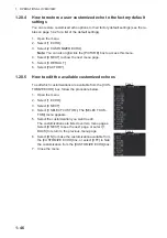
Reviews: