1. OPERATIONAL OVERVIEW
1-50
Note:
The position of the own ship marker and bearing scale change according to ref-
erence position and off-centering.
• [ANT]: When OFF CENTER is active, the bearing scale intervals change according-
ly.
• [CCRP]: When the CCRP moves outside the operational display area, the bearing
scale intervals may not be displayed correctly.
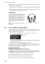
STERN UP mode
The STERN UP mode rotates the HEAD UP
mode picture, relative and true bearings and
display graphics 180°. This mode is useful on
dual-radar tugboats when backing up; one ra-
dar shows HEAD UP and another shows
STERN UP. To enable the STERN UP mode,
turn on [STERN UP] on the [OPERATION]
menu.
Note:
STERN UP mode is only available for
A/B/W-types.
1.31
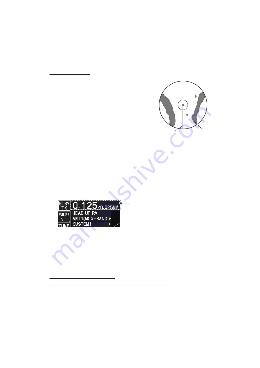
How to Select a Range Scale
The selected range scale and range ring interval are shown at the upper left corner on
the screen. When a target of interest comes closer, reduce the range scale so that it
appears in 50-90% of the display radius.
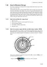
1. Place the cursor in the [RANGE] box at the top left corner of the screen.
In the above example, the range scale is set to 0.125 NM and the interval between
range rings is set to 0.025 NM.
2. Left-click to lower the range; right-click to raise the range.
You can also select the range with the
RANGE
key on the control unit. Press "+" to
increase the range, or press "-" to reduce the range. Press and hold a key to succes-
sively change the range upwards or downwards.
Changing the plotter range
(A/B/W-types with Radar Plotter functionality only)
With the radar in standby (STBY) mode, you can change the plotter range by pressing
the
RANGE
key. In this case, “range” means the on-screen displayed distance from
the left-hand edge of the screen to the right-hand edge of the screen.
[+]
: expands the range scale with the cursor location as the center.
[-]
: reduces the range scale with the cursor location as the center.
Press and hold the [+] or [-] key to change the range scale continuously.
Heading line
North marker
RANGE box
Summary of Contents for FAR-2218
Page 132: ...1 OPERATIONAL OVERVIEW 1 110 This page is intentionally left blank ...
Page 176: ...3 TARGET TRACKING TT 3 36 This page is intentionally left blank ...
Page 202: ...4 AIS OPERATION 4 26 This page is intentionally left blank ...
Page 232: ...5 VIDEO PLOTTER OPERATION 5 30 This page is intentionally left blank ...
Page 294: ......


