1. OPERATIONAL OVERVIEW
1-108
*: When the connected radar antenna is a magnetron-type, and the radar is assigned
as “Slave”, the desired value can be set for these functions. For SSD-types, this func-
tion cannot be controlled.
**: The desired value can be set when the radar is assigned as “Slave”, however the
maximum displayable range is dependent on the pulse setting at the “Master” radar.
1.58.2
Operating considerations for the dual radar display
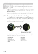
You can toggle each radar between standby and TX in the dual radar display. When
switching to standby on either radar, the Alert "EXT RADAR STBY" appears and the
radar echoes from the radar in standby are not displayed. Further, when switching to
standby, all TT targets are removed and tracking stops on the radar which is in stand-
by. However if a TT target is acquired on the radar which is not in standby, the TT in-
formation is passed to the radar which is in standby.
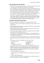
Changes made to the following functions are applied to both the own radar echoes
and the external echoes, on the display of the radar which made the changes. These
settings are not applied to the display of the external radar.
IR*
Dependent
Control
Desired value can be set
Cannot control
Tuning
TT LOST warning
Common
Control
Item Commonly Controlled Item Commonly Controlled
TT alerts ACK
TT acquire
• Off-center display
• CU/TM reset
• Presentation mode
• Range scale
• Electronic chart on/off
• Wiper
• Trail settings
• Echo stretch
• Echo Average
• Color Erase
• TT lost target filter
Radar Functions
Control
Master
Slave
Either radar enters
STBY mode
Boundary line is removed and display
shows only the Own radar echoes.
Summary of Contents for FAR-2218
Page 132: ...1 OPERATIONAL OVERVIEW 1 110 This page is intentionally left blank ...
Page 176: ...3 TARGET TRACKING TT 3 36 This page is intentionally left blank ...
Page 202: ...4 AIS OPERATION 4 26 This page is intentionally left blank ...
Page 232: ...5 VIDEO PLOTTER OPERATION 5 30 This page is intentionally left blank ...
Page 294: ......

