1. OPERATIONAL OVERVIEW
1-48
1.30
Orientation Modes
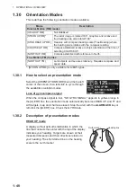
This radar has the following orientation modes available:
*: [STERN UP RM] is only available for A/B/W-types.
1.30.1
How to select an presentation mode
Select the [ORIENTATION MODE] box at the top left
corner of the screen, then left-click to cycle through
the available orientation modes.
Loss of gyrocompass signal
When the compass signal is lost, "NO GYRO SIGNAL" appears in yellow-orange in
the [ALERT] box, the orientation mode automatically becomes HEAD UP, and TT and
AIS targets, map and chart are erased. Stop the alert with the
ALARM ACK
key or
left-click the [ALERT] box. Check the GYRO data.
1.30.2
Description of presentation modes
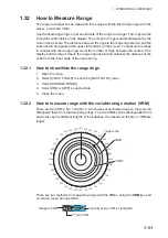
HEAD UP mode
A display without azimuth stabilization in which the
line that connects the center with the top of the display
indicates your heading. Targets are shown at their
measured distances and their directions relative to
your heading. The short dotted line on the bearing
scale is the north marker.
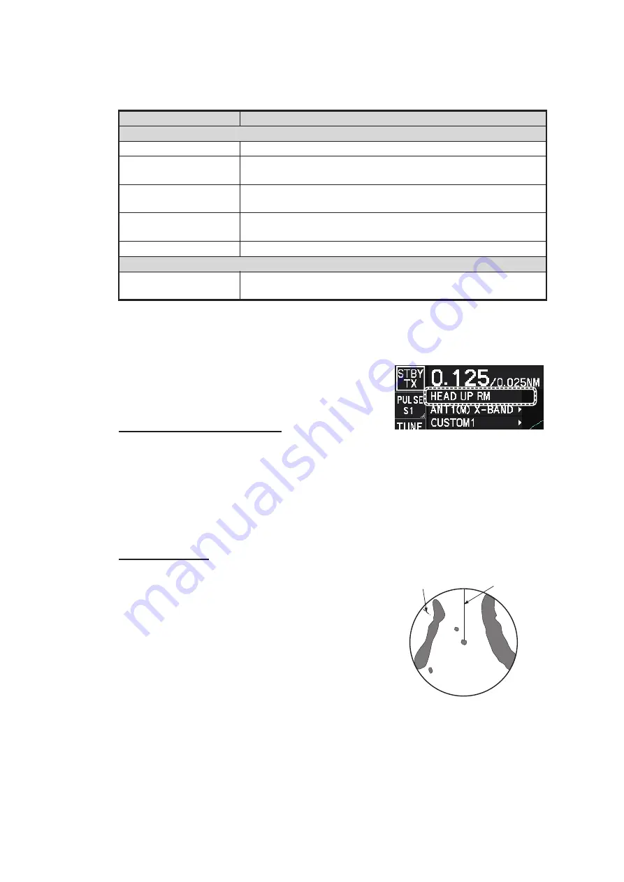
Mode
Description
Relative Motion (RM) modes
[HEAD UP RM]
Not stabilized
[STERN UP RM]*
The radar image is rotated 180°. Graphics and relative and
true bearings are also rotated 180°.
[STAB HEAD UP RM]
Head-up with compass bearing scale (True Bearing) where
the bearing scale rotates with the compass reading.
[COURSE UP RM]
Compass-stabilized relative to ship’s orientation at the time of
selecting COURSE UP.
[NORTH UP RM]
Compass-stabilized with reference to North.
True Motion (TM ) modes
[NORTH UP TM]
Land objects and sea are stationary. Requires compass and
speed data.
Heading line
North marker
Summary of Contents for FAR-2218
Page 132: ...1 OPERATIONAL OVERVIEW 1 110 This page is intentionally left blank ...
Page 176: ...3 TARGET TRACKING TT 3 36 This page is intentionally left blank ...
Page 202: ...4 AIS OPERATION 4 26 This page is intentionally left blank ...
Page 232: ...5 VIDEO PLOTTER OPERATION 5 30 This page is intentionally left blank ...
Page 294: ......


