2. WIRING
2-24
2.7
Sensor Adapters (option)
Maximum eight MC-3000S can be connected to a sensor network (for the redundant
connection: 16). The MC-3000S (serial input/output, IEC61162-2/1, 4ch) can connect
max. 10 sensor adapters using the MC1.5-W cables. The maximum number of MC-
3010A units is five.
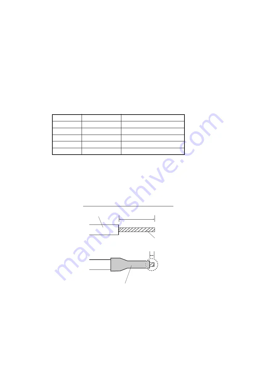
When fabricating the MC1.5-W cables, use the lot terminal (ferrule type, supplied) to
maintain performance. This fabrication requires the optional crimping tool (type:
CRIMPFOX 10S). For the relations between the connectors and rod terminals, see
page AP-2. Also, the stickers attached on the reverse side of the covers show the de-
tailed connections.
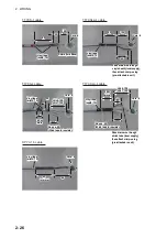
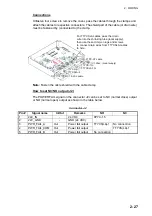
Attache the cables to the applicable pins.
Use the ferrule-type terminals (supplied) to connect the cables to the terminals in the
sensor adapters. This connection requires a crimping tool (CRIMPFOX10S, option).
Note 1:
Use the MC1.5-W cable between the sensor adapters.
Note 2:
The total length of the MC1.5-W cables should be less than 6 m to prevent
malfunction.
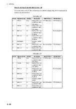
Pin No.
Cable color
Signal
1
Red
24V_OUT or 24V_IN
2
Black
24V_GND
3
White
MODBUS-A
4
Blue
MODBUS-B
5
Gray
GND
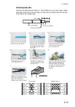
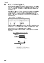
Rod terminal (ferrule type):
After attaching the rod terminal, use the
optional crimping tool CRIMPFOX 10S
to crimp.
6mm
0.5 to 1 mm
How to attach the rod terminal (ferrule type)
Core
Vinyl sheath
Summary of Contents for FCR-2139S-BB
Page 74: ...2 WIRING 2 48 This page is intentionally left blank ...
Page 136: ...D 1 14 Feb 2011 Y NISHIYAMA ...
Page 137: ...D 2 Y Hatai ...
Page 138: ...May17 07 R Esumi D 3 ...
Page 139: ...13 Feb 2014 H MAKI D 4 ...
Page 140: ...D 5 24 May 2012 Y NISHIYAMA ...
Page 141: ...D 6 24 May 2012 Y NISHIYAMA ...
Page 142: ...D 7 24 May 2012 Y NISHIYAMA ...
Page 143: ...D 8 ...
Page 144: ...D 9 ...
Page 145: ...D 10 ...
Page 148: ...13 Jan 2012 Y NISHIYAMA 西山義浩 D 13 ...
Page 149: ...13 Jan 2012 Y NISHIYAMA D 14 ...
Page 150: ...D 15 ...


